GM Service Manual Online
For 1990-2009 cars only
Makes
🢒
GMC_Truck
🢒
2005
🢒
GMC Sierra Denali
🢒
Vehicle Control Systems
🢒
Vehicle DTC Information
🢒 Starting and Charging Schematics
Starting and Charging Schematics Except HP2
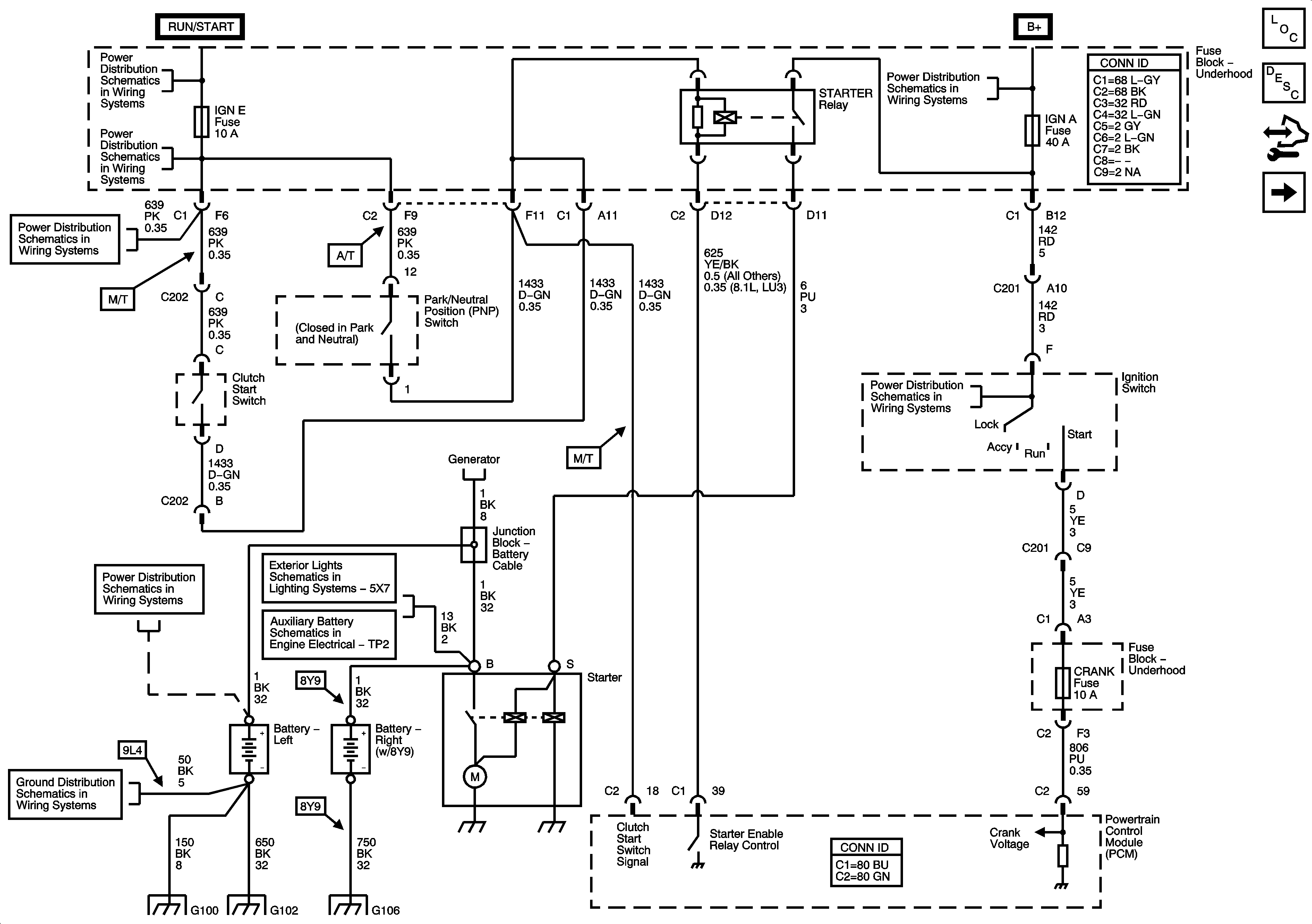
Figure
1:
Starting - Gas
Master Electrical Component List
Starting System Description and Operation
Control Module References
Starting - Diesel
Ignition Switch - ACC/RUN and RUN/START Bus Bars and IGN B Fuse
IGN E and AIRBAG Fuses
B+ Bar Bus
Ignition Switch - START, RUN, and ACC/RUN/START Bus Bars and IGN A and CRANK Fuses
Charging - 10 Series (Except HP2)
Battery Supply - 1 of 2
Wrecker Lighting - 5X7
Auxiliary Battery
G100, G101, and G102
G104, G106, G107 and G110
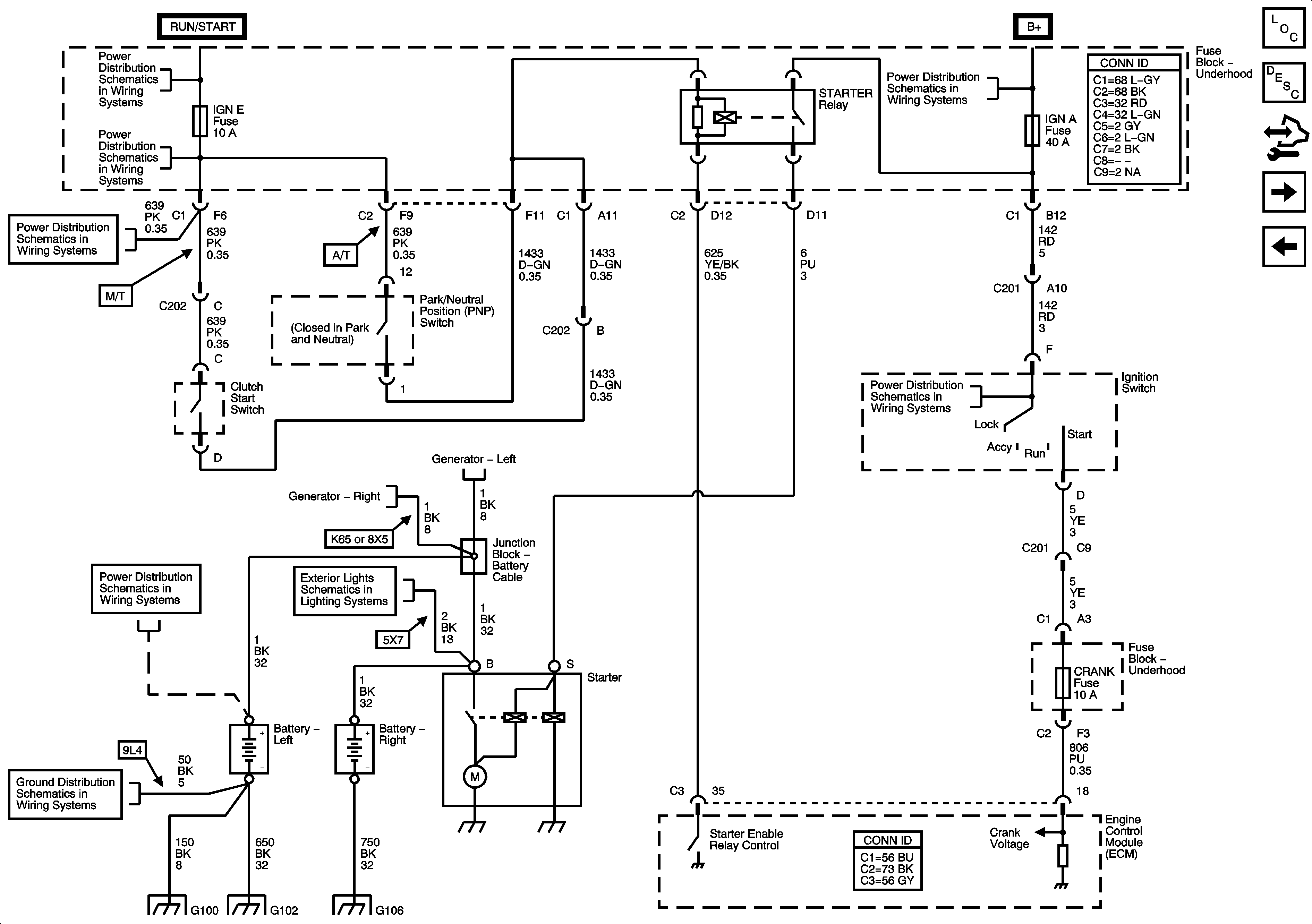
Figure
2:
Starting - Diesel
Master Electrical Component List
Starting System Description and Operation
Control Module References
Charging - 20/30 Series and HP2
Starting - Gas
Ignition Switch - ACC/RUN and RUN/START Bus Bars and IGN B Fuse
IGN E and AIRBAG Fuses
B+ Bar Bus
Charging - Diesel
Charging - Diesel
Ignition Switch - START, RUN, and ACC/RUN/START Bus Bars and IGN A and CRANK Fuses
Battery Supply - 1 of 2
Wrecker Lighting - 5X7
G100, G101, and G102
G104, G106, G107 and G110
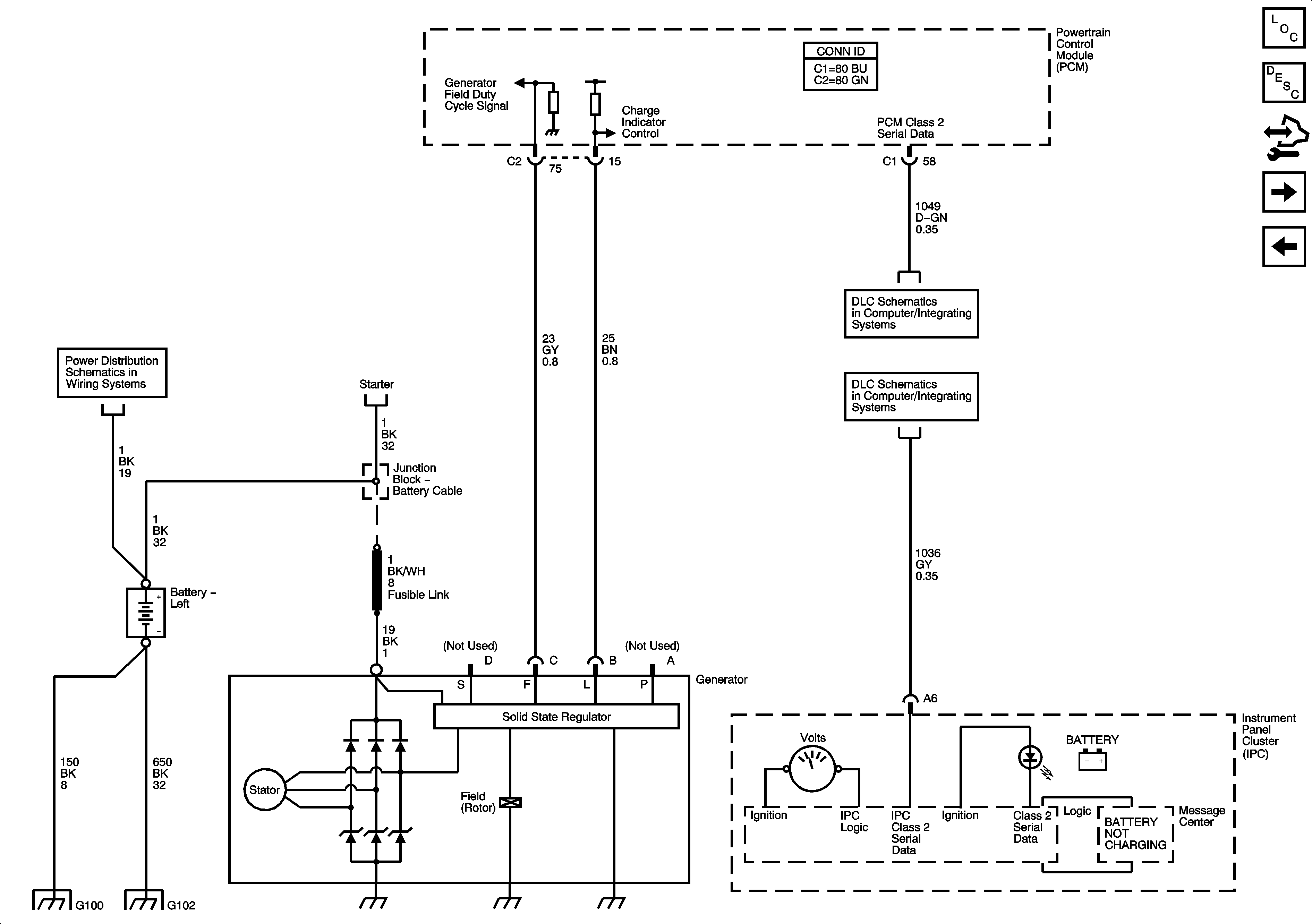
Figure
3:
Charging - 20/30 Series and HP2
Master Electrical Component List
Charging System Description and Operation W/O Generator/Battery Control Module
Control Module References
Charging - 10 Series (Except HP2)
Starting - Diesel
Battery Supply - 1 of 2
Starting - Gas
Power, Ground, DLC and Splice Pack SP 205
G100, G101, and G102
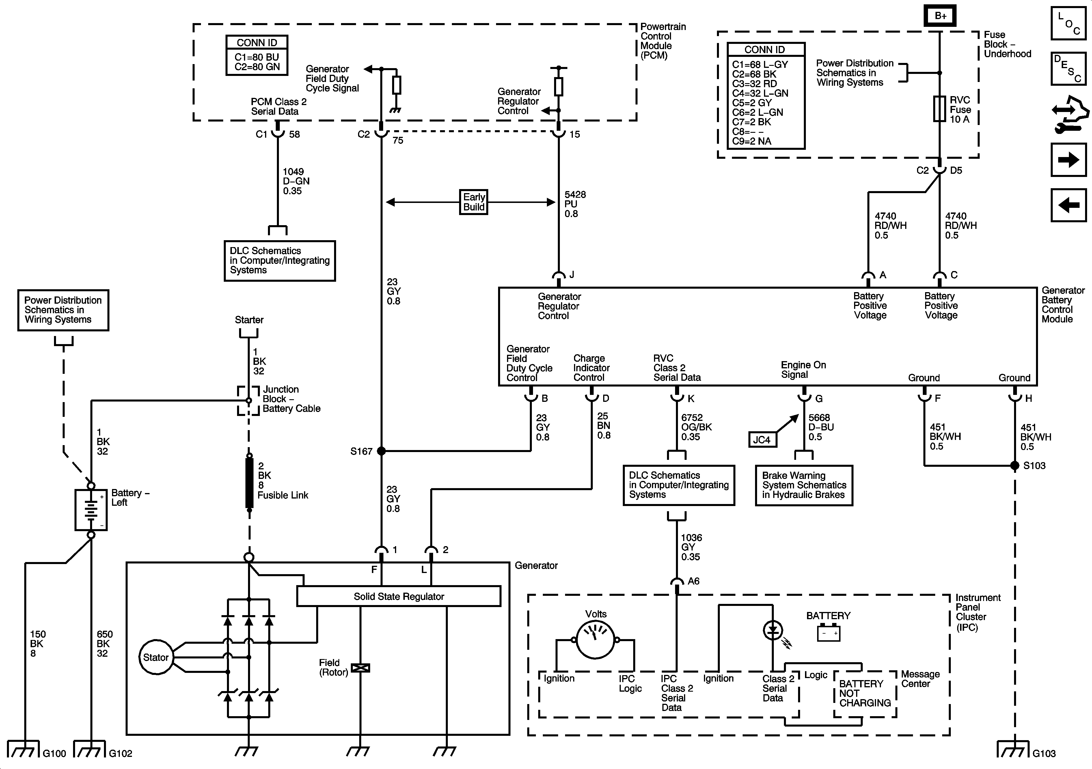
Figure
4:
Charging - 10 Series (Except HP2)
Master Electrical Component List
Charging System Description and Operation Generator/Battery Control Module
Control Module References
Charging - Diesel
Charging - 20/30 Series and HP2
B+ Bar Bus
Battery Supply - 1 of 2
Power, Ground, DLC and Splice Pack SP 205
Charging - 20/30 Series and HP2
Power, Ground, DLC and Splice Pack SP 205
Supplimental Brake Assist
G100, G101, and G102
G103 - Gas
Figure
5:
Charging - Diesel
Master Electrical Component List
Charging System Description and Operation W/O Generator/Battery Control Module
Control Module References
Charging - 10 Series (Except HP2)
Power, Ground, DLC and Splice Pack SP 205
Battery Supply - 1 of 2
G100, G101, and G102
G104, G106, G107 and G110
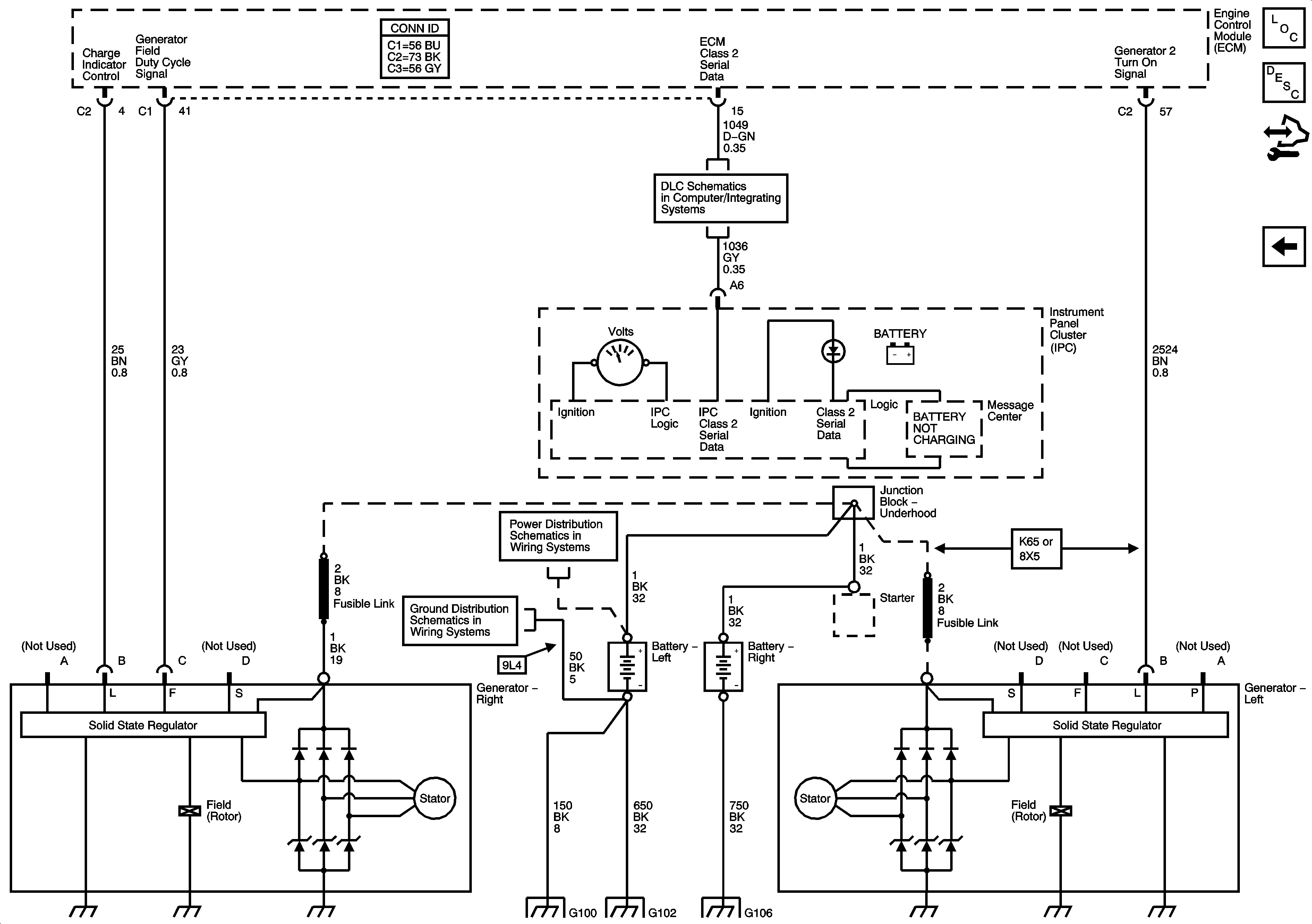
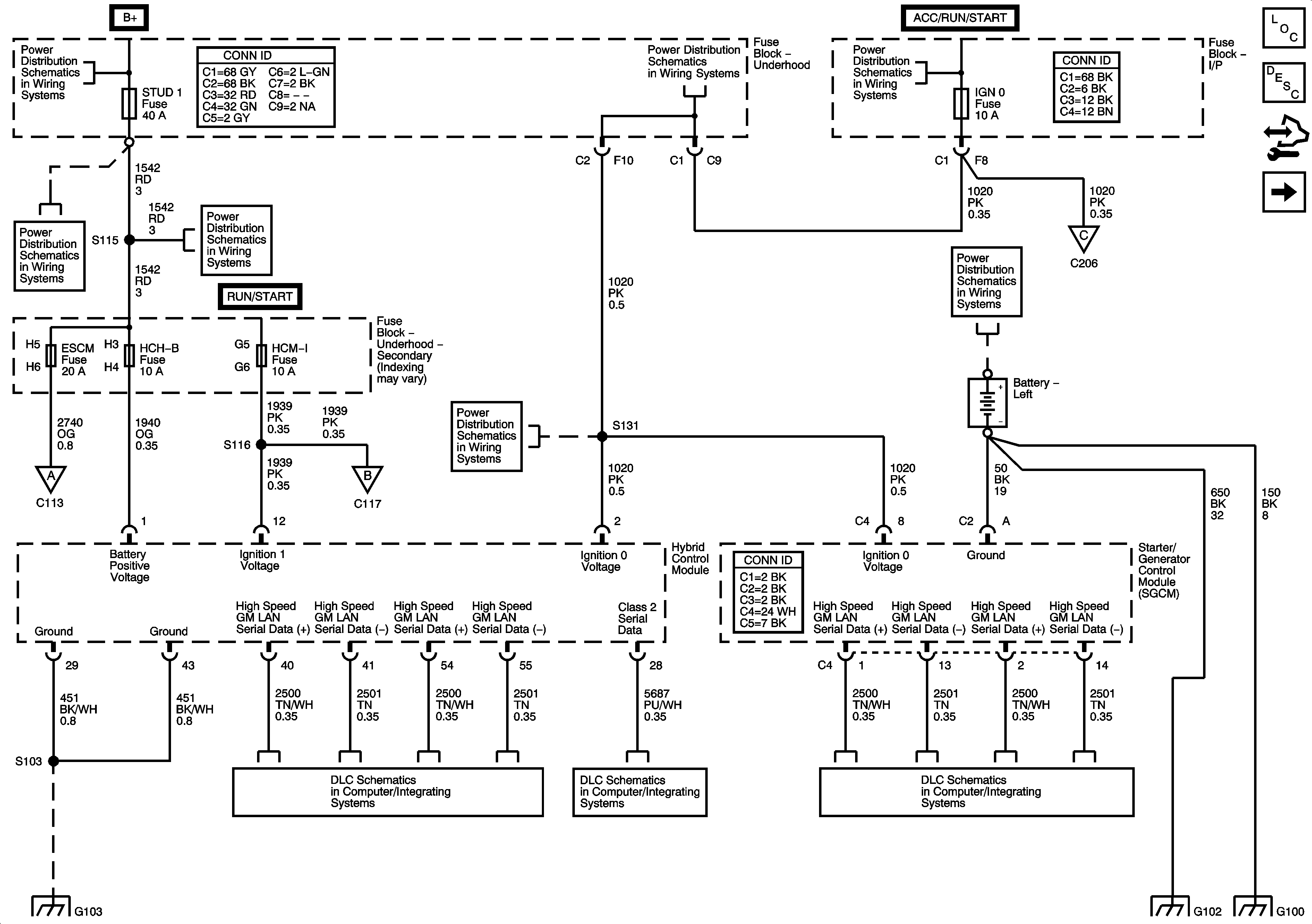
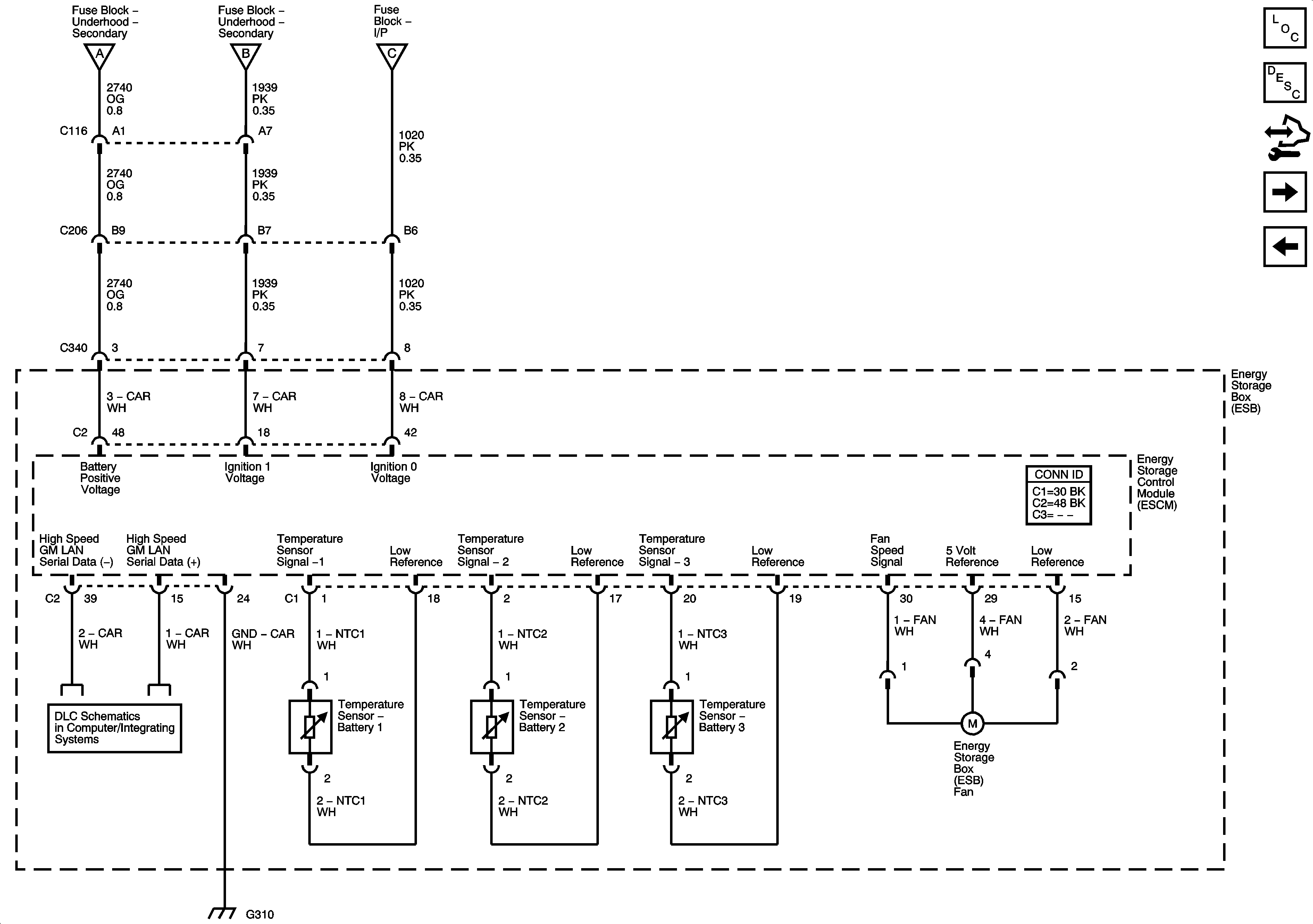
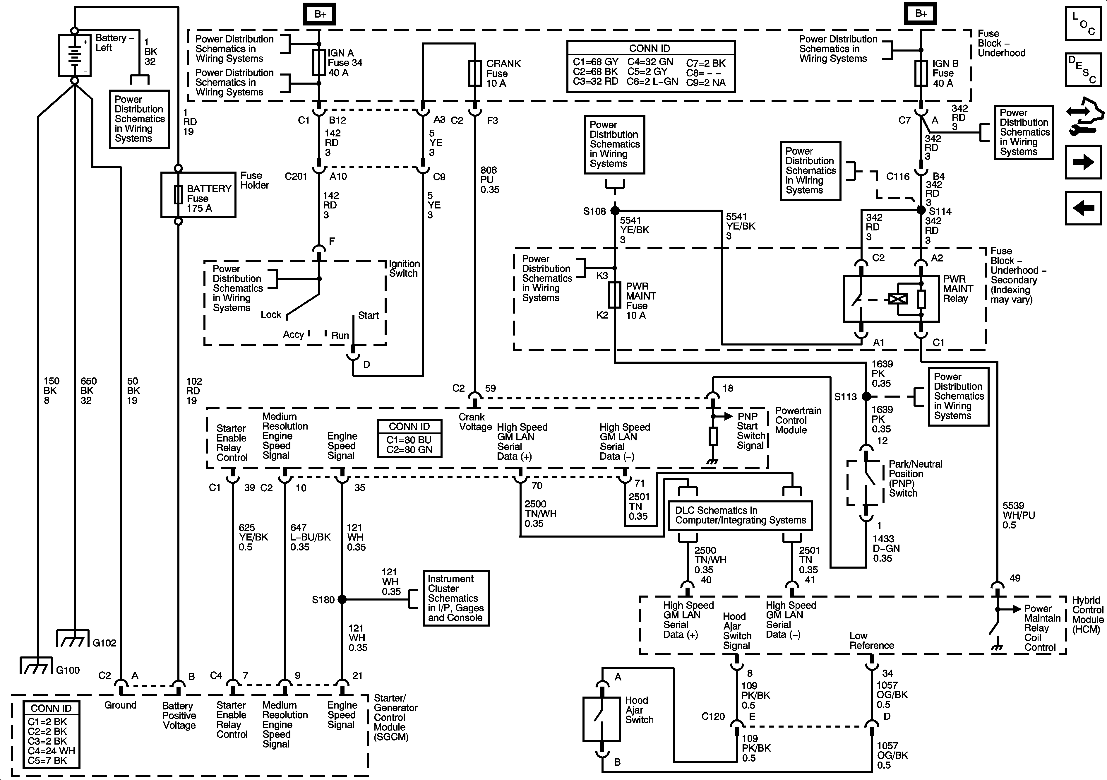
Starting and Charging Schematics HP2
Figure
1:
Power, Ground, Serial Data, Hybrid Control Module and SGCM - 1 of 2
Master Electrical Component List
Starter/Generator Control Module Description and Operation
Control Module References
Power, Ground, Serial Data and ESCM - 2 of 2
B+ Bar Bus
IGN 0, RR WPR, SEO ACCY, TBC ACCY, TBC IGN 0, and WS WPR Fuses
Ignition Switch - START, RUN, and ACC/RUN/START Bus Bars and IGN A and CRANK Fuses
Power, Ground, Serial Data and ESCM - 2 of 2
ABS, AUX HTR PMP, ESCM, HCM-B, MBEC 1, RTD, STUD1, STUD2, TRANS PUMP, VSES/ECAS Fuses and RT DOORS and SEAT Circuit Breakers
Power, Ground, Serial Data and ESCM - 2 of 2
IGN 0, RR WPR, SEO ACCY, TBC ACCY, TBC IGN 0, and WS WPR Fuses
G103 - Gas
High Speed GM LAN (HP2)
Power, Ground, DLC and Splice Pack SP 205
High Speed GM LAN (HP2)
Figure
2:
Power, Ground, Serial Data and ESCM - 2 of 2
Master Electrical Component List
Starter/Generator Control Module Description and Operation
Control Module References
Starting 1 of 2 and Engine Speed Signal
Power, Ground, Serial Data, Hybrid Control Module and SGCM - 1of 2
High Speed GM LAN (HP2)
Figure
3:
Starting - 1 of 2 and Engine Speed Signal
Master Electrical Component List
Starter/Generator Control Module Description and Operation
Control Module References
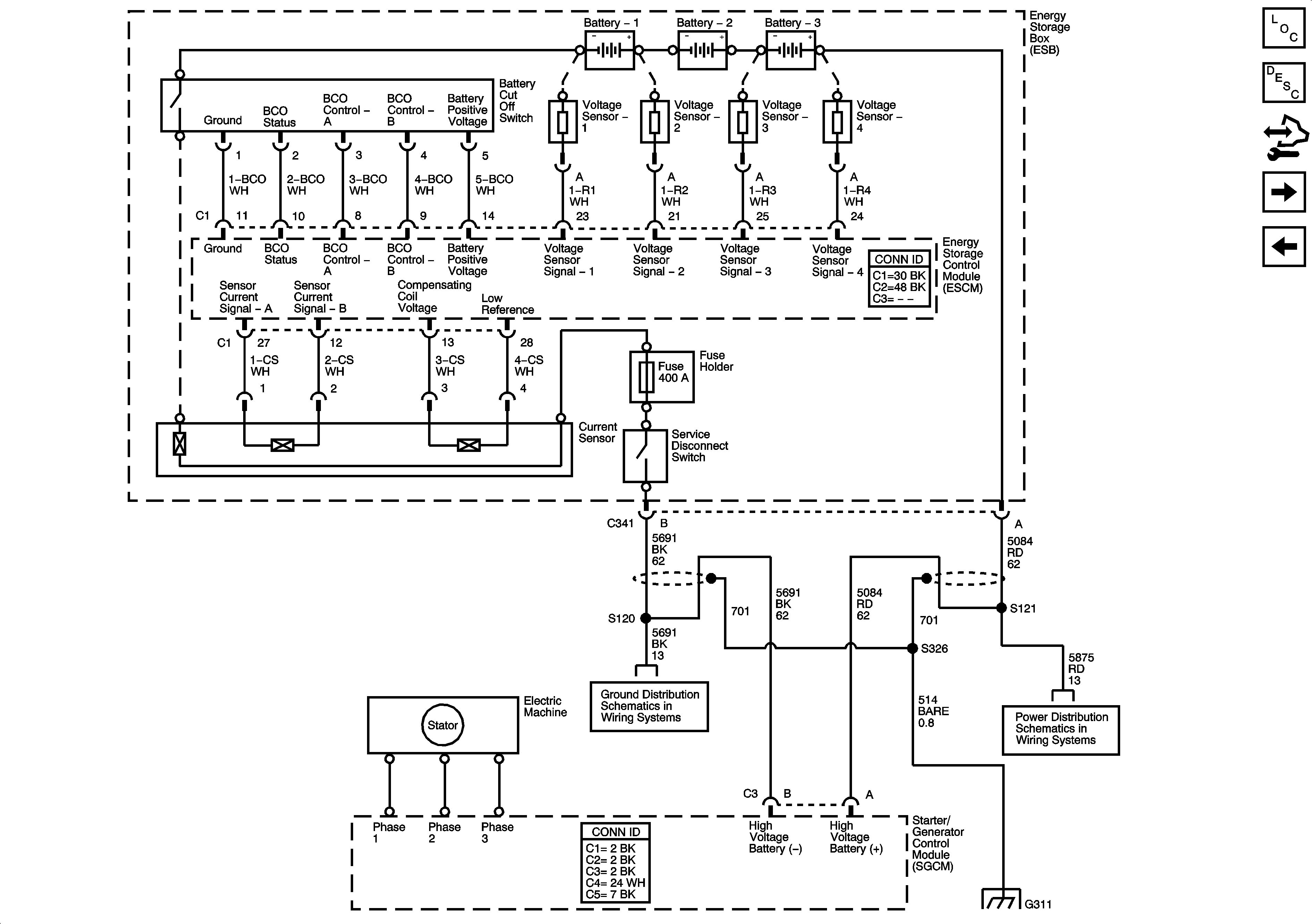
Starting - 2 of 2 and Energy Storage
Power, Ground, Serial Data and ESCM - 2 of 2
B+ Bar Bus
Ignition Switch - START, RUN, and ACC/RUN/START Bus Bars and IGN A and CRANK Fuses
B+ Bar Bus
Battery Supply - 1 of 2
COOL PMP, HYBRID 02A, HYBRID O2B, IGN B and PWR MAINT Fuses
Ignition Switch - ACC/RUN and RUN/START Bus Bars and IGN B Fuse
Ignition Switch - START, RUN, and ACC/RUN/START Bus Bars and IGN A and CRANK Fuses
COOL PMP, HYBRID 02A, HYBRID O2B, IGN B and PWR MAINT Fuses
Gages, Vehicle Speed Signal, Engine Oil Pressure, and Fuel Level Sensors
Power, Ground, DLC and Splice Pack SP 205
G100, G101, and G102
Figure
4:
Starting - 2 of 2 and Energy Storage
Master Electrical Component List
Starter/Generator Control Module Description and Operation
Control Module References
Controlled/Monitored Subsystem Reference
Starting 1 of 2 and Engine Speed Signal
G120, G121, G122, G310, G311 and G405 (HP2)
Battery Supply - 2 of 2
G120, G121, G122, G310, G311 and G405 (HP2)
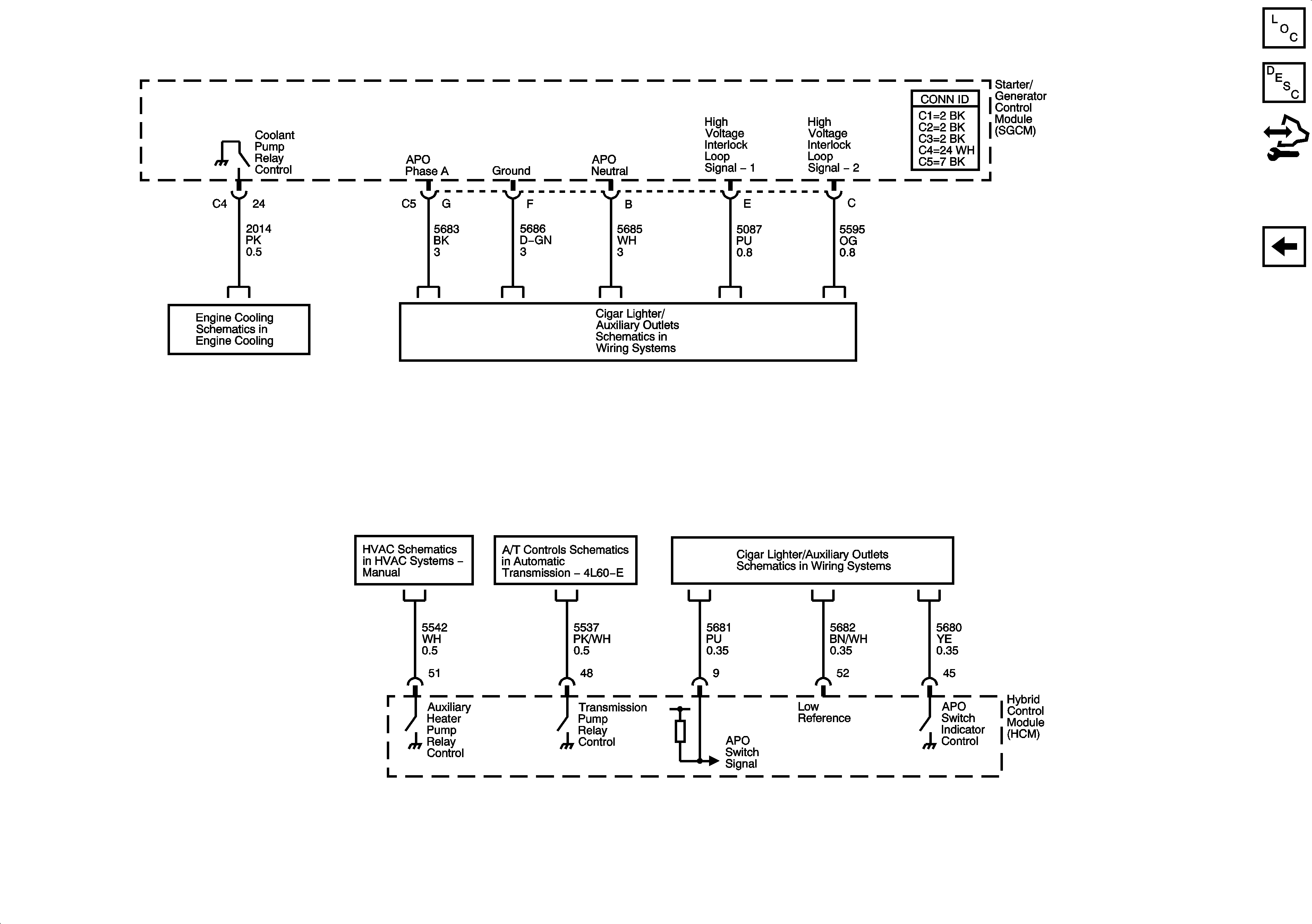
Figure
5:
Controlled/Monitored Subsystem Reference
Master Electrical Component List
Starter/Generator Control Module Description and Operation
Control Module References
Starting - 2 of 2 and Energy Storage
HP2
120V AC Outlets (HP2) - 2 of 2
Auxiliary Heater Pump (HP2)
Auxiliary Pump Controls - HP2
120V AC Outlets (HP2) - 2 of 2