Removal Procedure
- Remove the control valve assembly from the transmission. Refer to Control Valve Body Replacement .
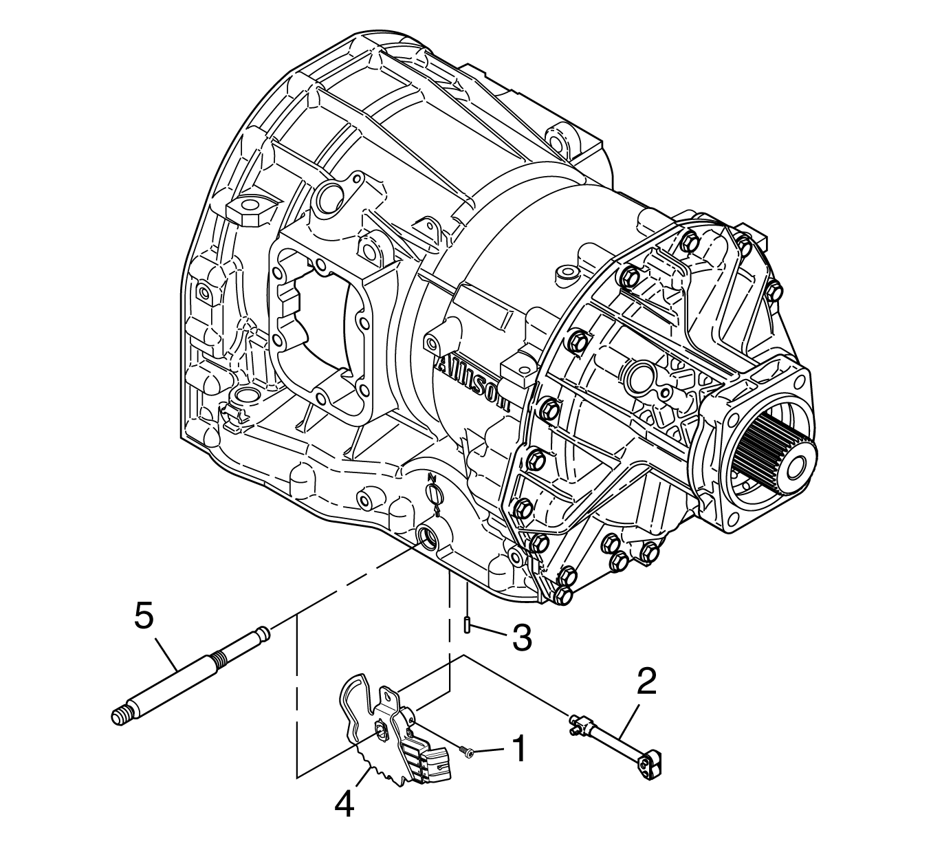
- Remove the detent lever/IMS retaining bolt (1) using a T27 TORX® bit and discard the retaining bolt.
- Place a protective plate on the transmission case surface around the spherical pin (3). Remove the spherical pin (3) from the transmission case.
- Slide the manual shift shaft (5) through the detent lever/IMS assembly (4) and through the manual shift shaft seal.
- Rotate the detent lever/IMS assembly to disengage the park pawl apply assembly (2). Remove the detent lever/IMS assembly (4).

Important: The detent lever/IMS retaining bolt contains patch lock material on the threads. Do not reuse the retaining bolt.
Notice: DO NOT mar the transmission case surface around the spherical pin when removing or installing the spherical pin. An unmarred surface is required to maintain the seal between the control valve assembly and the transmission case.
Notice: DO NOT twist the spherical pin when removing the pin from the transmission case. Damage to the transmission case can occur.
Installation Procedure
- Place the new detent lever/IMS assembly (4) in position in the transmission case. Rotate the detent lever/IMS assembly to engage the park pawl apply assembly (2). Reinstall the manual shift shaft (5) through the manual shift shaft seal and through the detent lever/IMS assembly (4).
- Push the manual shift shaft (5) into the final position in the transmission case.
- Install the spherical pin (3) into the transmission case that retains the manual shift shaft.
- Install the detent lever/IMS retaining bolt (1) using a T27 TORX® bit.
- Install the control valve assembly. Refer to Control Valve Body Replacement .
- Perform the FastLearn procedure. Refer to FastLearn Procedure .

Notice: Use the correct fastener in the correct location. Replacement fasteners must be the correct part number for that application. Fasteners requiring replacement or fasteners requiring the use of thread locking compound or sealant are identified in the service procedure. Do not use paints, lubricants, or corrosion inhibitors on fasteners or fastener joint surfaces unless specified. These coatings affect fastener torque and joint clamping force and may damage the fastener. Use the correct tightening sequence and specifications when installing fasteners in order to avoid damage to parts and systems.
Tighten
Tighten the bolt (1) to 10 N·m (92 lb in).
Important: The FastLearn, adapt, procedure must be performed. This can be done in 1 step using a scan tool. If this procedure is not done, the TCM adaptive values will be at the settings that it learned for the old components and will be in slow adaptive mode. Under these conditions, it will take an unacceptably long time for the adaptive values to converge to levels suitable for the new transmission.
