Front Disc Brake Hardware Replacement 1500 Series
Caution: Refer to Brake Dust Caution in the Preface section.
Removal Procedure
- Inspect the fluid level in the brake master cylinder reservoir.
- If the fluid level is midway between the maximum-full point, and the minimum allowable level, no fluid needs to be removed from the reservoir before proceeding.
- If the fluid level is higher than midway between the maximum-full point, and the minimum allowable level, remove fluid to the midway point before proceeding.
- Remove the tire and wheel assembly. Refer to Tire and Wheel Removal and Installation .
- Compress the brake caliper pistons.
- Remove the brake caliper bolts.
- Remove the caliper from the caliper bracket.
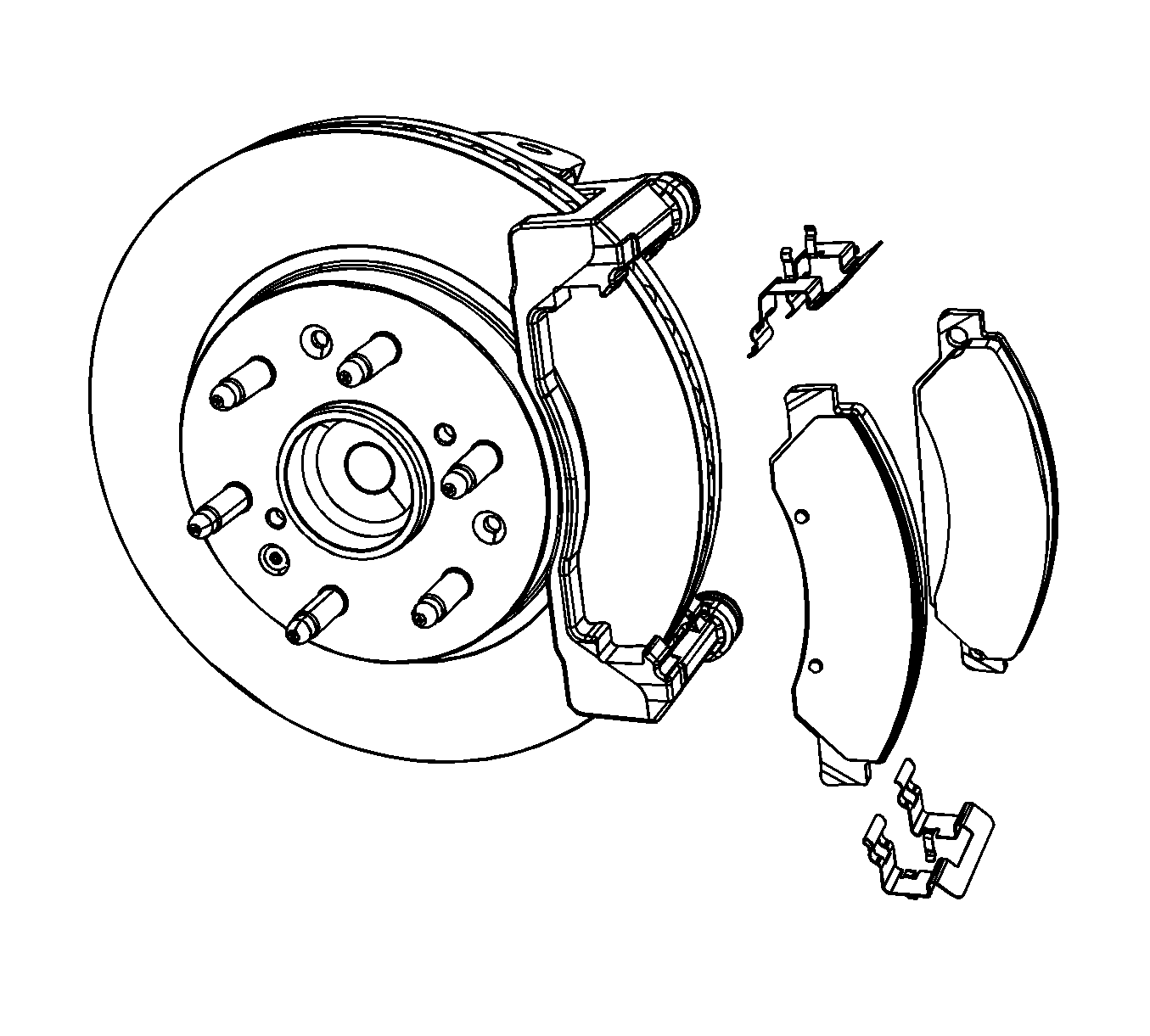
- Remove the brake pads from the caliper bracket.
- Remove the brake pad retainers.
- Inspect the disc brake hardware. Refer to Front Disc Brake Mounting and Hardware Inspection .
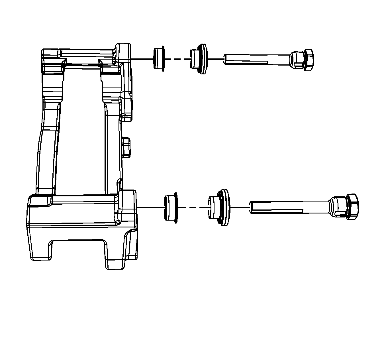
- Remove the caliper pins, seals, and bushings from the caliper bracket.
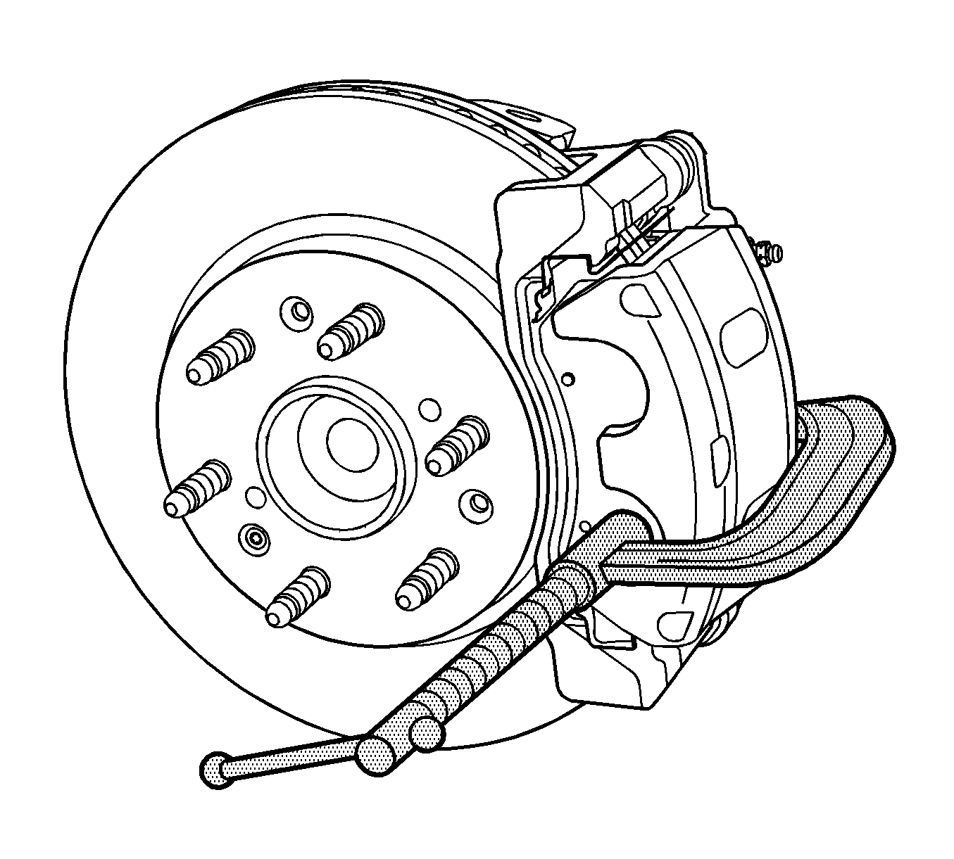
| 5.1. | Install 2 large C-clamps over the top of the caliper housing and against the back of the outboard pad. |
| 5.2. | Slowly tighten the C-clamps until the pistons are pushed completely into the caliper bores. |
| 5.3. | Remove the C-clamps from the caliper. |
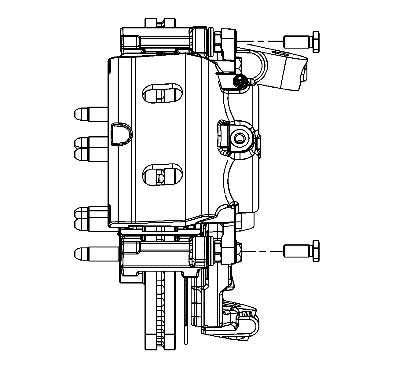
Caution: Do not depress the brake pedal with the brake rotors/calipers and/or the brake drums removed. Damage to the brake system may result. If brake system damage occurs and is not repaired, vehicle damage and/or personal injury or death may result.
Notice: Refer to Brake Caliper Notice in the Preface section.
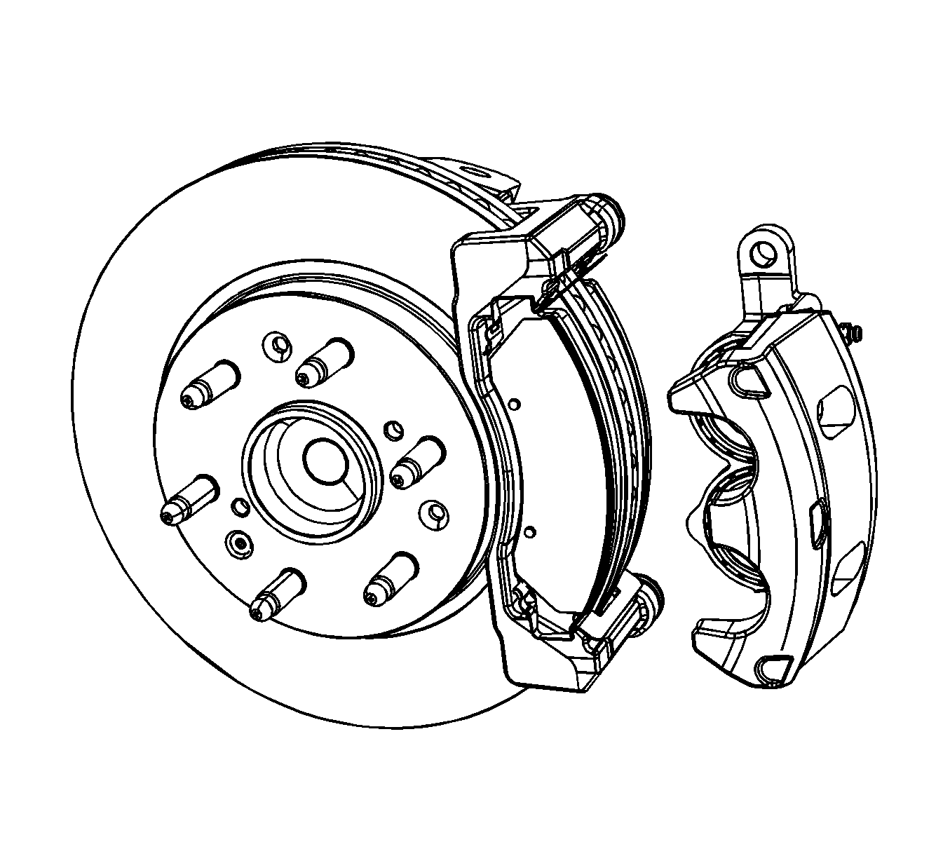
Support the caliper with heavy mechanic's wire or equivalent. DO NOT disconnect the hydraulic brake hose from the caliper.
Installation Procedure
- Lubricate the caliper bushings, bolts and seals with high temperature silicone brake lubricant.
- Install the caliper pin bushings, seals and pins to the caliper bracket.
- Install the brake pad retainers to the caliper bracket.
- Install the brake pads.
- Install the caliper to the caliper bracket.
- Install the brake caliper bolts.
- Install the tire and wheel assembly. Refer to Tire and Wheel Removal and Installation .
- With the engine OFF, gradually apply the brake pedal approximately 2/3 of its travel distance.
- Slowly release the brake pedal.
- Wait 15 seconds, then repeat steps 6-7 until a firm brake pedal is obtained. This will properly seat the caliper pistons and pads.
- Fill the master cylinder reservoir to the proper level with clean brake fluid, if necessary. Refer to Master Cylinder Reservoir Filling .


Notice: Refer to Fastener Notice in the Preface section.

Tighten
Tighten the bolts to 100 N·m (74 lb ft).
Front Disc Brake Hardware Replacement 2500 Series
Caution: Refer to Brake Dust Caution in the Preface section.
Removal Procedure
- Inspect the fluid level in the brake master cylinder reservoir.
- If the fluid level is midway between the maximum-full point, and the minimum allowable level, no fluid needs to be removed from the reservoir before proceeding.
- If the fluid level is higher than midway between the maximum-full point, and the minimum allowable level, remove fluid to the midway point before proceeding.
- Remove the tire and wheel assembly. Refer to Tire and Wheel Removal and Installation .
- Compress the brake caliper pistons.
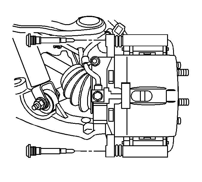
- Remove the brake caliper bolts.
- Remove the caliper from the caliper bracket.
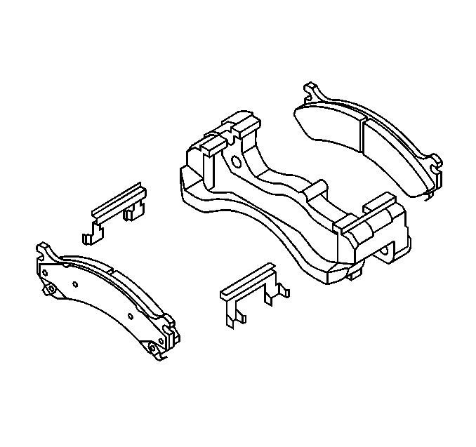
- Remove the brake pads from the caliper bracket.
- Remove the brake pad retainers.
- Inspect the disc brake hardware. Refer to Front Disc Brake Mounting and Hardware Inspection .
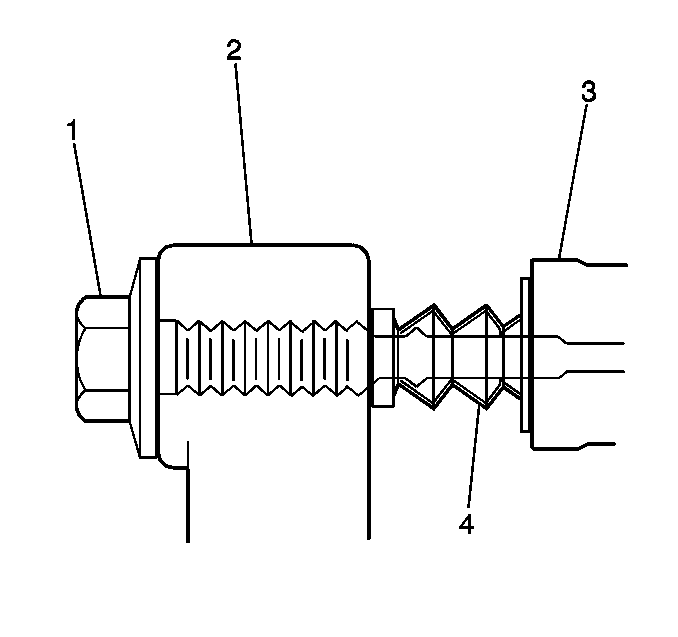
- Remove the caliper pin boots (4) from the caliper bracket (3).
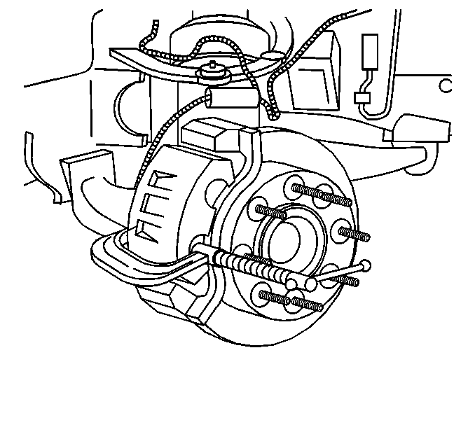
| 5.1. | Install 2 large C-clamps over the top of the caliper housing and against the back of the outboard pad. |
| 5.2. | Slowly tighten the C-clamps until the pistons are pushed completely into the caliper bores. |
| 5.3. | Remove the C-clamps from the caliper. |
Caution: Do not depress the brake pedal with the brake rotors/calipers and/or the brake drums removed. Damage to the brake system may result. If brake system damage occurs and is not repaired, vehicle damage and/or personal injury or death may result.
Notice: Refer to Brake Caliper Notice in the Preface section.
Support the caliper with heavy mechanic's wire or equivalent. DO NOT disconnect the hydraulic brake flexible hose from the caliper.
Installation Procedure
- Lubricate the caliper bushings, bolts and seals with high temperature silicone brake lubricant.
- Install the caliper pin boots (4) to the caliper bracket (3).
- Install the brake pad retainers to the caliper bracket.
- Install the brake pads.
- Install the caliper to the caliper bracket.
- Install the brake caliper bolts.
- Install the tire and wheel assembly. Refer to Tire and Wheel Removal and Installation .
- With the engine OFF, gradually apply the brake pedal approximately 2/3 of its travel distance.
- Slowly release the brake pedal.
- Wait 15 seconds, then repeat steps 6-7 until a firm brake pedal is obtained. This will properly seat the caliper pistons and pads.
- Fill the master cylinder reservoir to the proper level with clean brake fluid, if necessary. Refer to Master Cylinder Reservoir Filling .


Notice: Use the correct fastener in the correct location. Replacement fasteners must be the correct part number for that application. Fasteners requiring replacement or fasteners requiring the use of thread locking compound or sealant are identified in the service procedure. Do not use paints, lubricants, or corrosion inhibitors on fasteners or fastener joint surfaces unless specified. These coatings affect fastener torque and joint clamping force and may damage the fastener. Use the correct tightening sequence and specifications when installing fasteners in order to avoid damage to parts and systems.
Tighten
Tighten the bolts to 108 N·m (80 lb ft).
