Tools Required
J 33163 Valve Tray Set
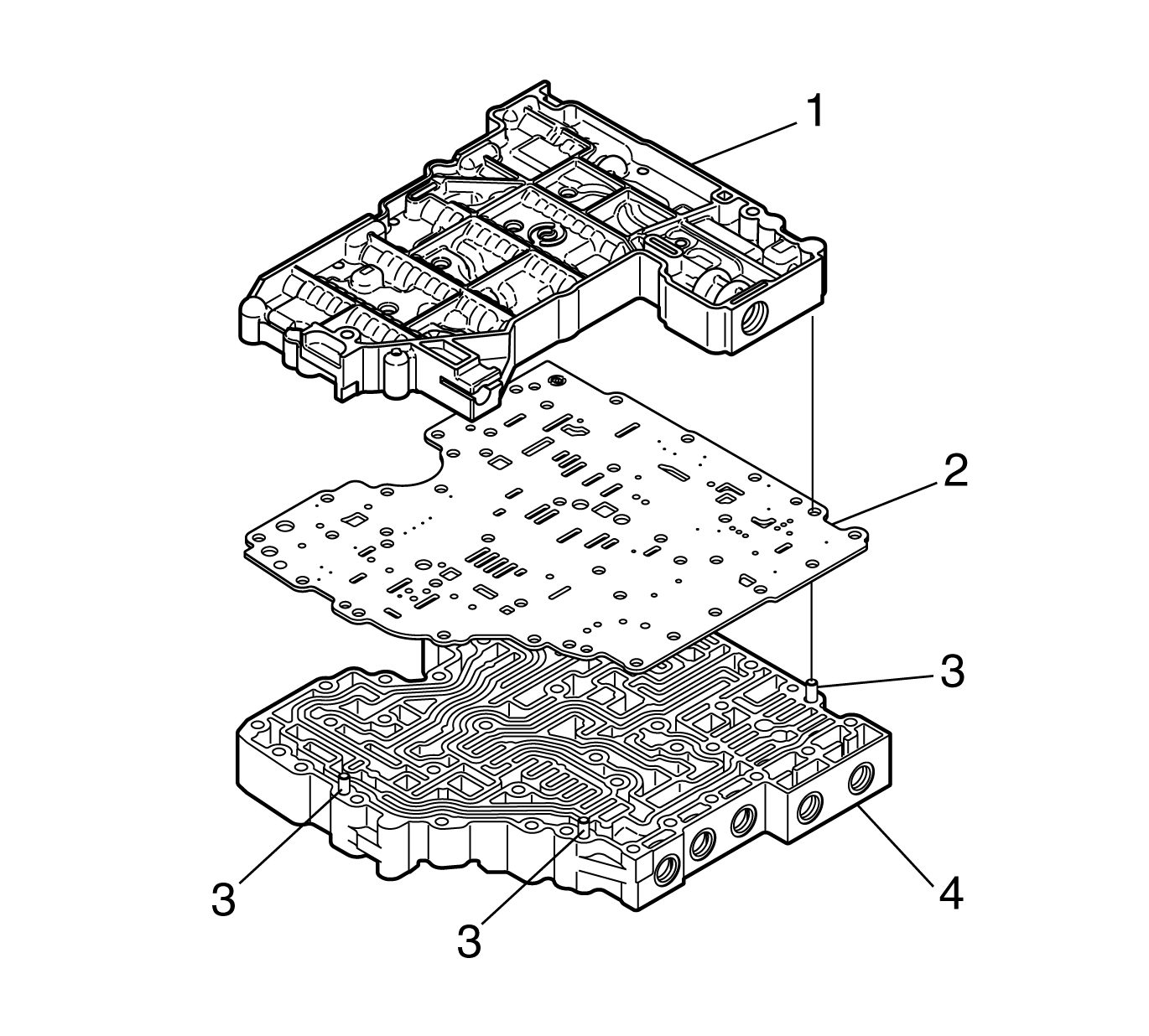
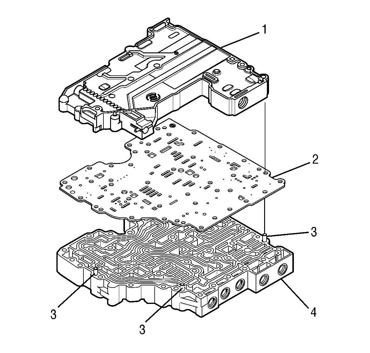
- Position the main valve body assembly (4) on the work table so that the worm-track side is up.
- Align the separator plate (2) with the main valve body locating pins (3).
- Install the separator plate (2).
- Align the shift valve body assembly (1) with the main valve body locating pins (3).
- Install the shift valve body assembly onto the separator plate.
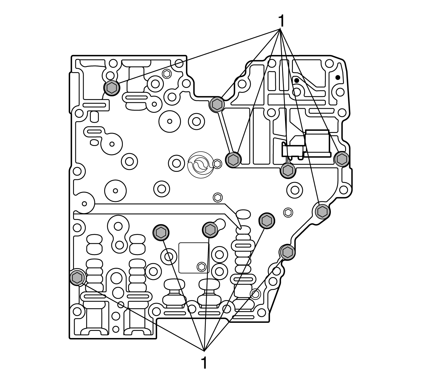
- Position the control valve body assembly on the work table so that the main valve body is facing up.
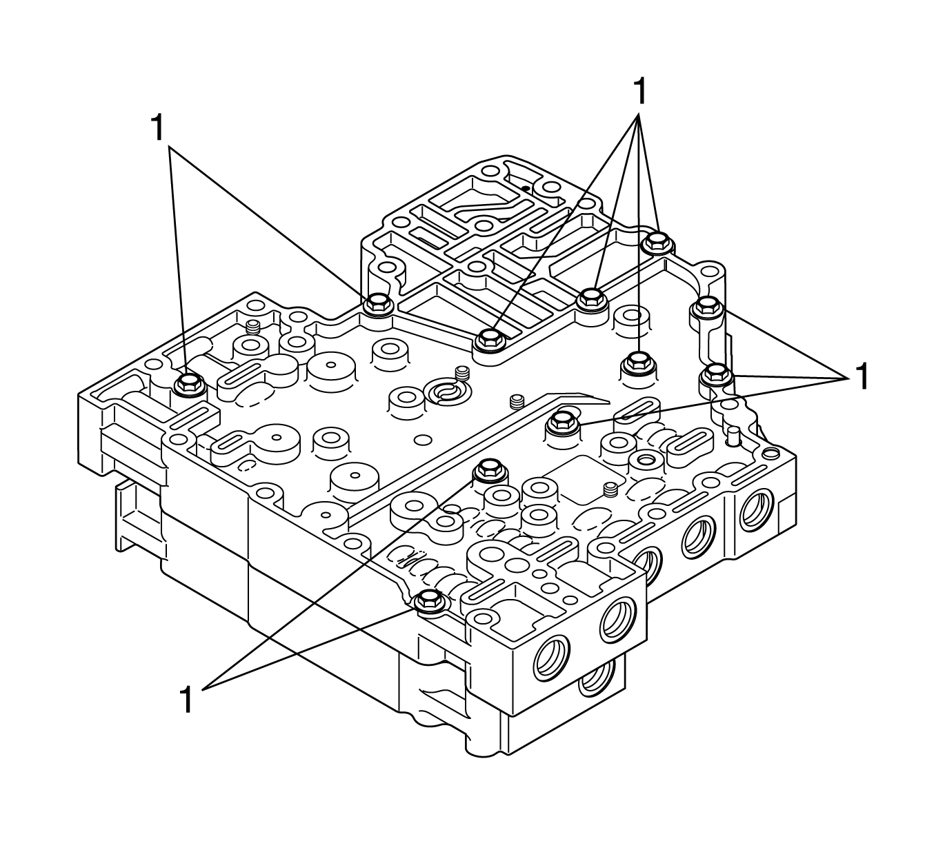
- Install 11 bolts (1) retaining the valve bodies together.
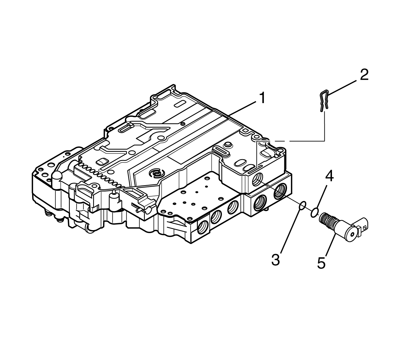
- Position the control valve body assembly on the work table so that the shift valve body is up.
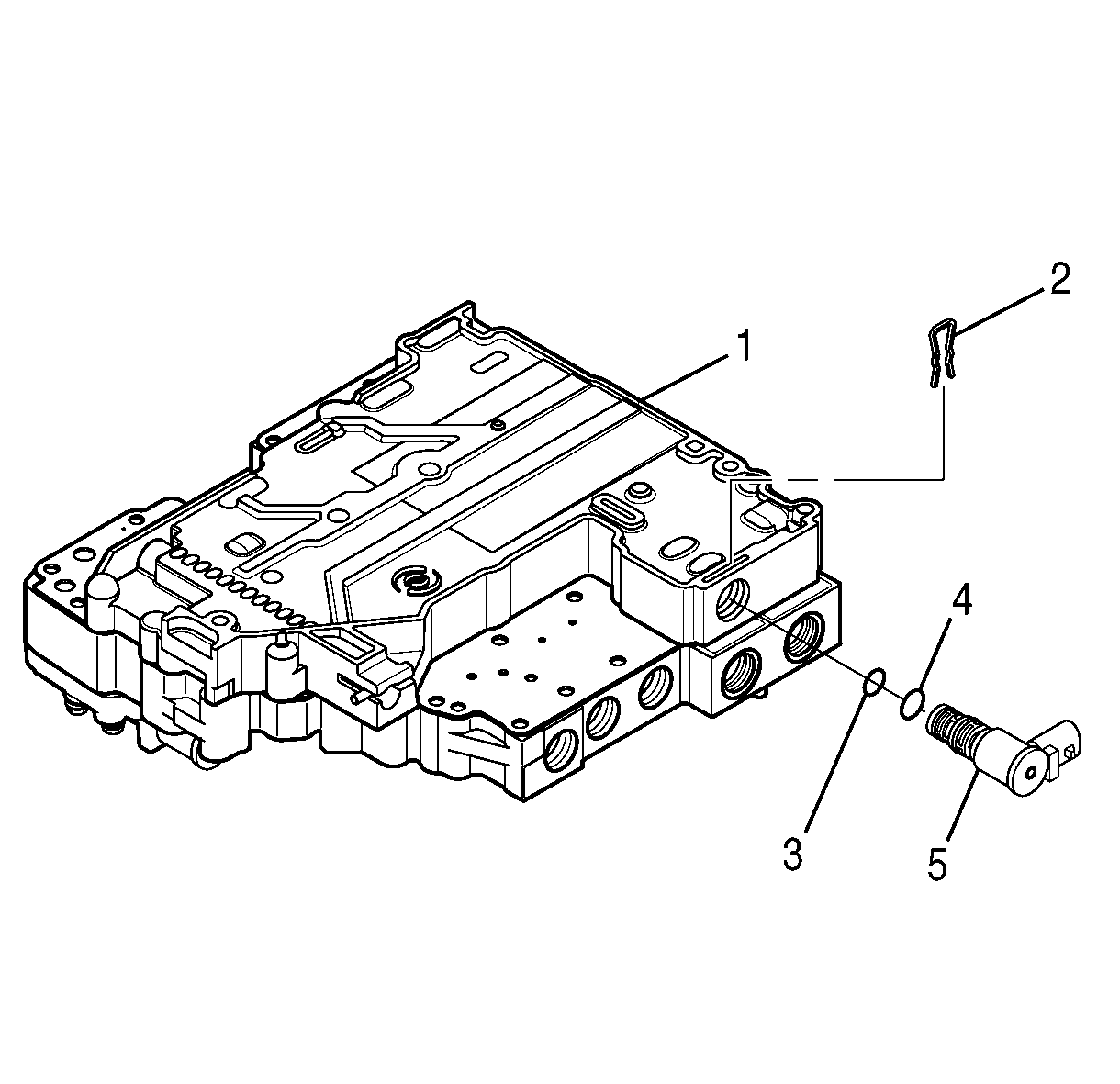
- Install the solenoid O-ring (4) onto the SS1 (5).
- Install the solenoid O-ring (3) onto the SS1 (5).
- Align the SS1 (5) so that the electrical connector points away from the nearest locating pin and is parallel to the separator plate as shown.
- Push the solenoid into the valve body until the solenoid seats.
- Install the solenoid retainer (2).
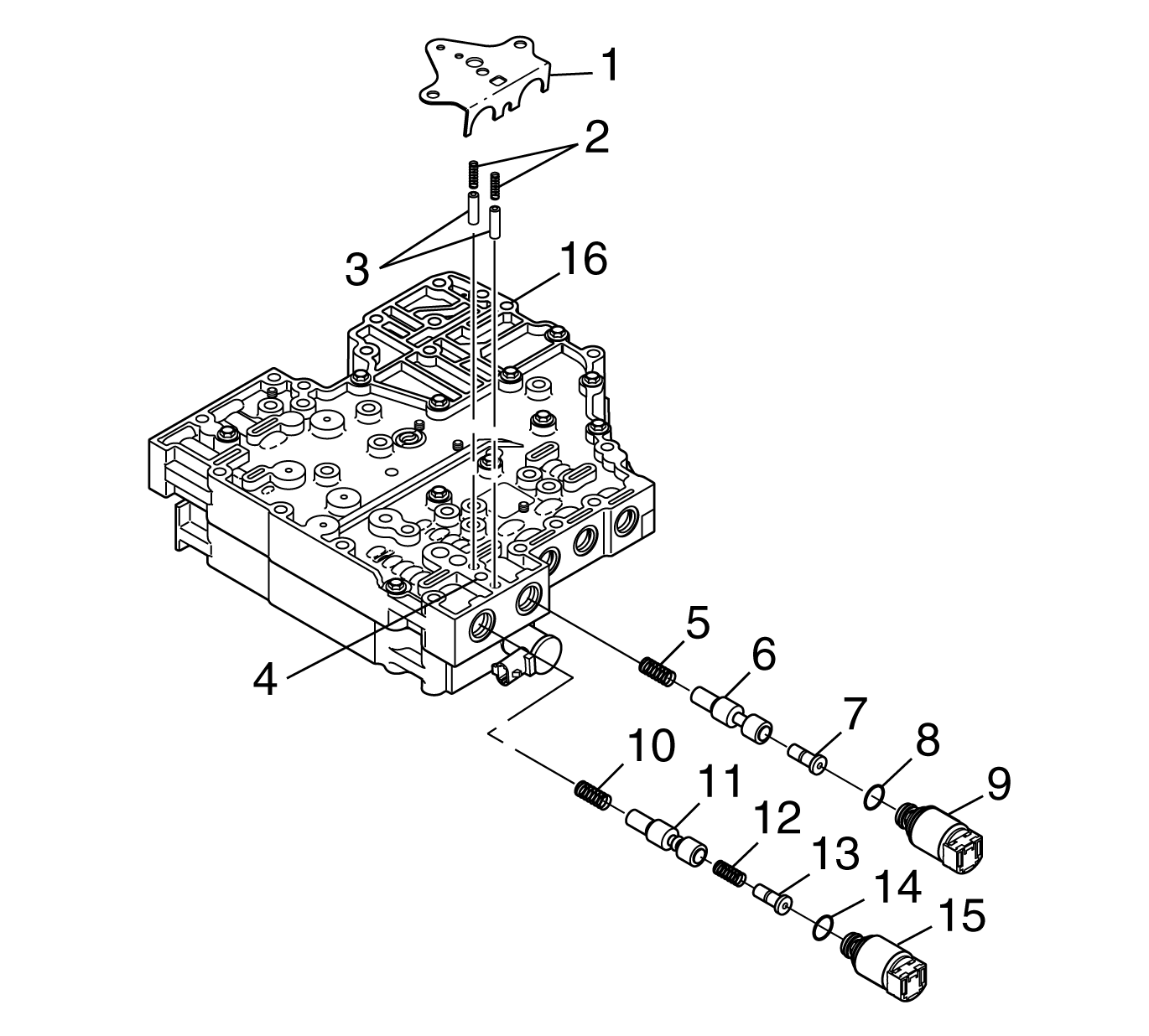
- Position the control valve assembly on the work table so that the main valve body (16) is facing up.
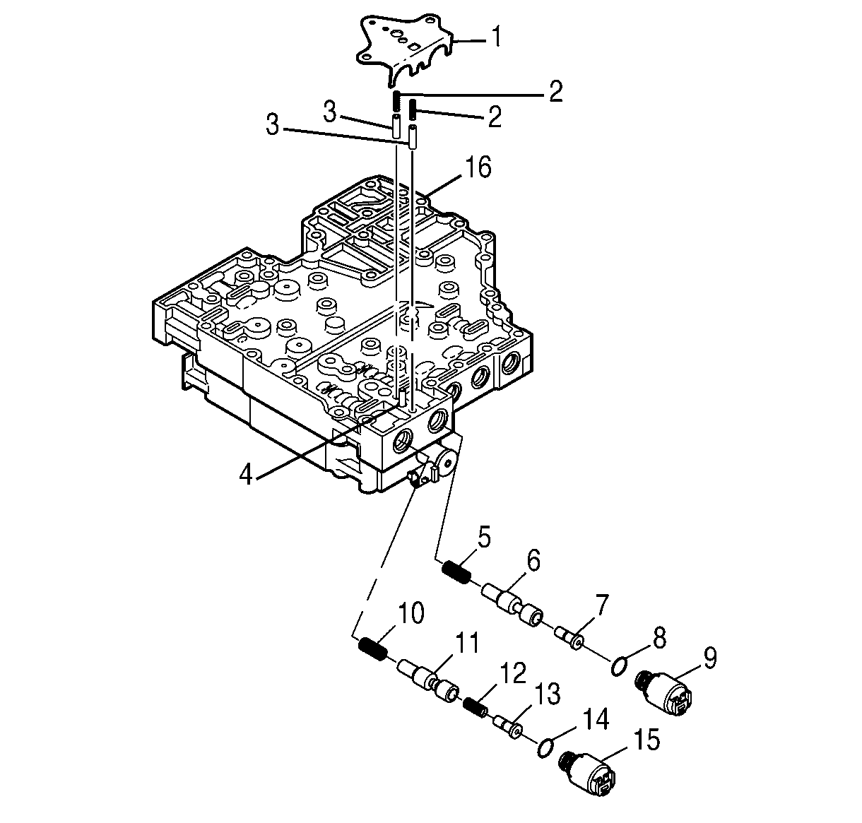
- Install the solenoid O-ring (14) onto the PCS1 (15).
- Install the solenoid O-ring (8) onto the PCS2 (9).
- Install the spring (10), PCS1 valve (11), spring (12), and trim gain valve (13).
- Install the spring (5), PCS2 valve (6), and trim gain valve (7).
- Install PCS1 (15) so that the electrical connection faces up. Do not seat the solenoid.
- Install PCS2 (9) so the electrical connection faces up. Do not seat the solenoid.
- Align 2 accumulator plugs (3) so that their spring bores face up.
- Install 2 accumulator plugs (3) and 2 accumulator springs (2).
- Push PCS1 and PCS2 into the bores until the solenoids seat.
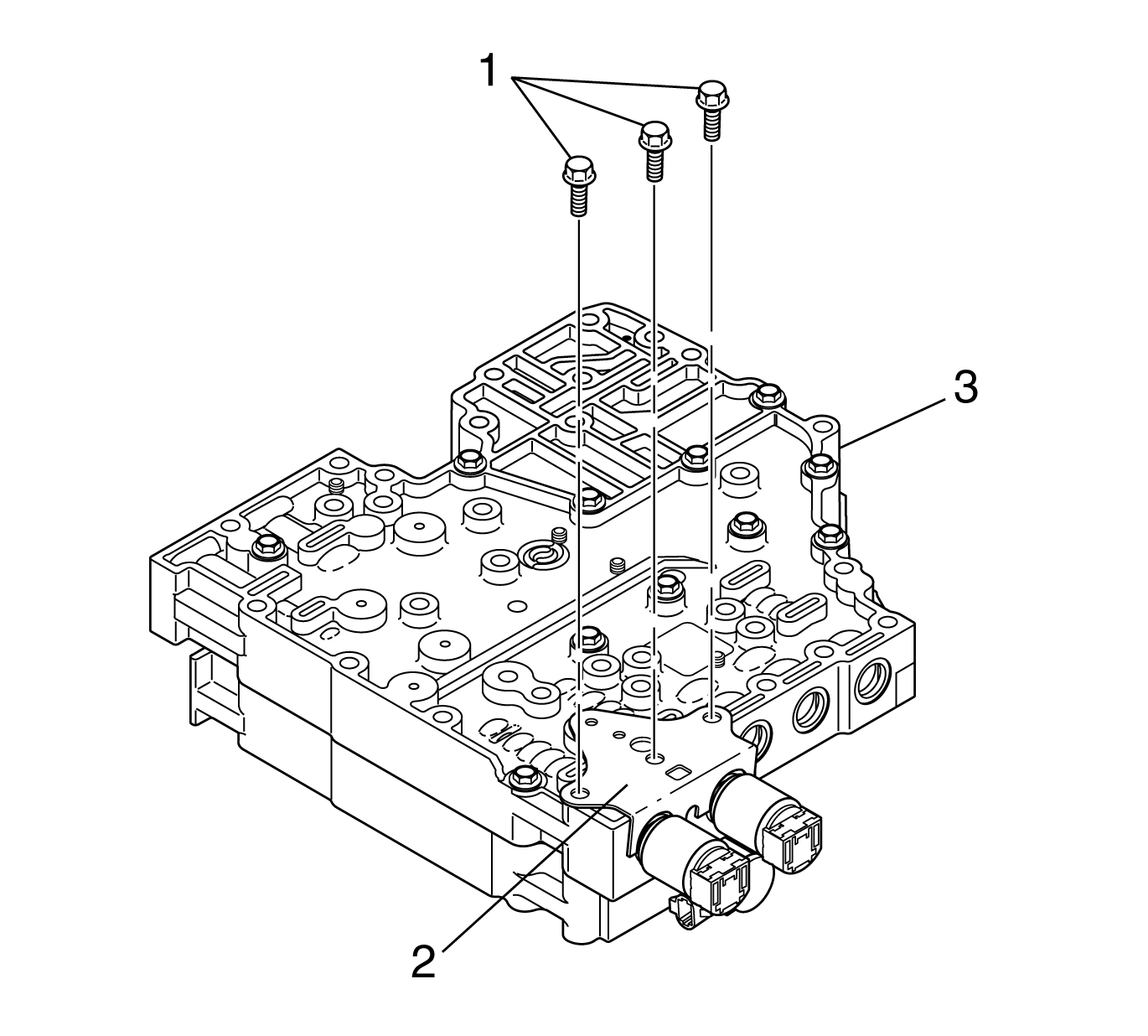
- Align the PCS1 and PCS2 retaining bracket (1) with the main valve body locating pin (4).
- Install the PCS1 and PCS2 retaining bracket (1) so that the PCS1, PCS2, accumulator plugs, and accumulator springs are retained against the valve body.
- Install 3 bolts (1) retaining the PCS1 and PCS2 retaining bracket (2).
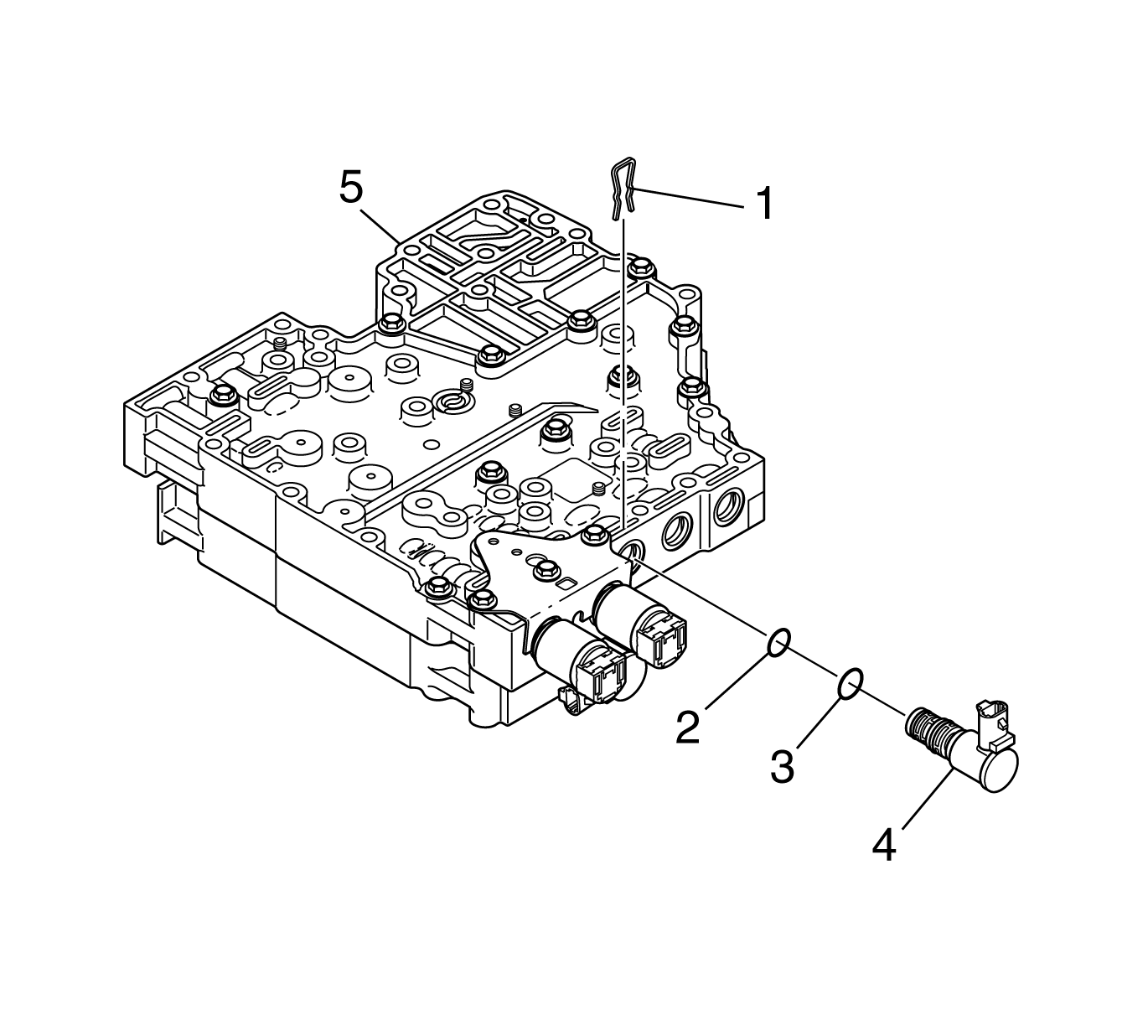
- Install the solenoid O-ring (3) onto the SS3 (4).
- Install the solenoid O-ring (2) onto the SS3 (4).
- Install the SS3 (4) so that the electrical connection faces up. Seat the solenoid.
- Install the solenoid retainer (1).
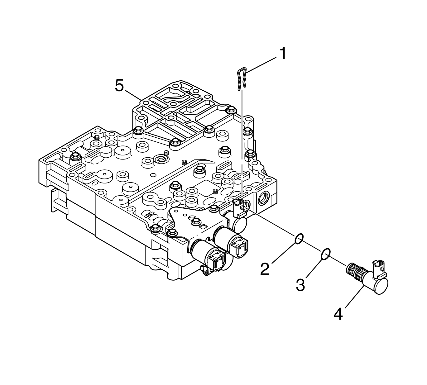
- Install the solenoid O-ring (3) onto the SS2 (4).
- Install the solenoid O-ring (2) onto the SS2 (4).
- Install the SS2 (4) so that the electrical connection faces up. Seat the solenoid.
- Install the solenoid retainer (1).
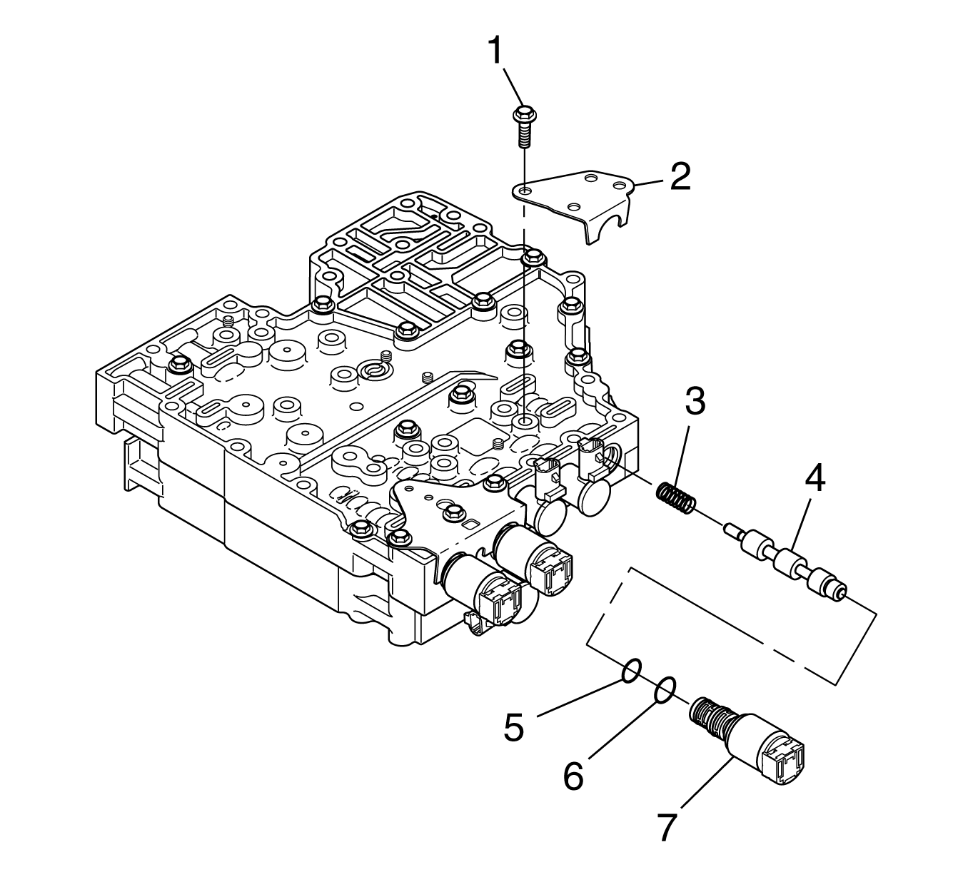
- Install the solenoid O-ring (6) onto the torque converter clutch (TCC) PCS (7).
- Install the solenoid O-ring (5) onto the TCC PCS (7).
- Install the TCC PCS spring (3).
- Install the TCC PCS valve (4).
- Align the TCC PCS (7) so that the electrical connection faces up.
- Install the TCC PCS (7). Seat the solenoid.
- Install the solenoid bracket (2).
- Install the solenoid bracket bolt (1).
- Install O-ring (3) onto the modulated main pressure (MAIN MOD) solenoid (4).
- Install O-ring (2) onto the modulated main pressure (MAIN MOD) solenoid (4).
- Install the MAIN MOD solenoid (4) into the modulated main pressure valve body (1), pointing the connector toward the TFP switch.
- Install the solenoid retainer (5) from the bottom into the MAIN MOD solenoid valve body.
- Install the 6 speed tube into the MAIN MOD solenoid valve body.
- Align the modulated main pressure valve body (2) with the bolt holes in the main valve body (3).
- Install the 2 bolts (1) retaining the modulated main pressure valve body (2) to the main valve body.
- Align the bolts holes and alignment tabs of the transmission fluid pressure (TFP) switch (1) with the corresponding holes in the main valve body (1).
- Install the TFP switch (1) onto the main valve body (3).
- Install the reverse signal pipe (2) onto the main valve body.
- Install five bolts (1) and one bolt (2) retaining the TFP switch to the main valve body.
- Install two bolts (3) retaining the reverse signal pipe to the main valve body.
Tighten
Tighten the bolts to 12 N·m (9 lb ft).
Important: To help prevent confusing parts on assembly, J 33163 has been used to store the removed control valve assembly valves, springs, and stops during disassembly.
Important:
• The O-ring (4) is slightly larger than the O-ring (3). • P/N 29536833 is printed on the shift solenoid 1 (SS1) (5).
Notice: DO NOT damage the solenoids when turning over the control valve assembly.
Important: P/N 29541895 is printed on pressure control solenoid 1 (PCS1).
Important: P/N 29541896 is printed on the PCS2.
Tighten
Tighten the bolts to 12 N·m (9 lb ft).
Important:
• The solenoid O-rings are brown. • The O-ring (3) is slightly larger than the O-ring (2). • P/N 29536833 is printed on the SS3.
Important:
• The solenoid O-rings are brown. • The O-ring (3) is slightly larger than the O-ring (2). • P/N 29542206 is printed on the SS2.
Important:
• The solenoid O-rings are brown. • The O-ring (6) is slightly larger than the O-ring (5).
Tighten
Tighten the bolt to 12 N·m (108 lb in).
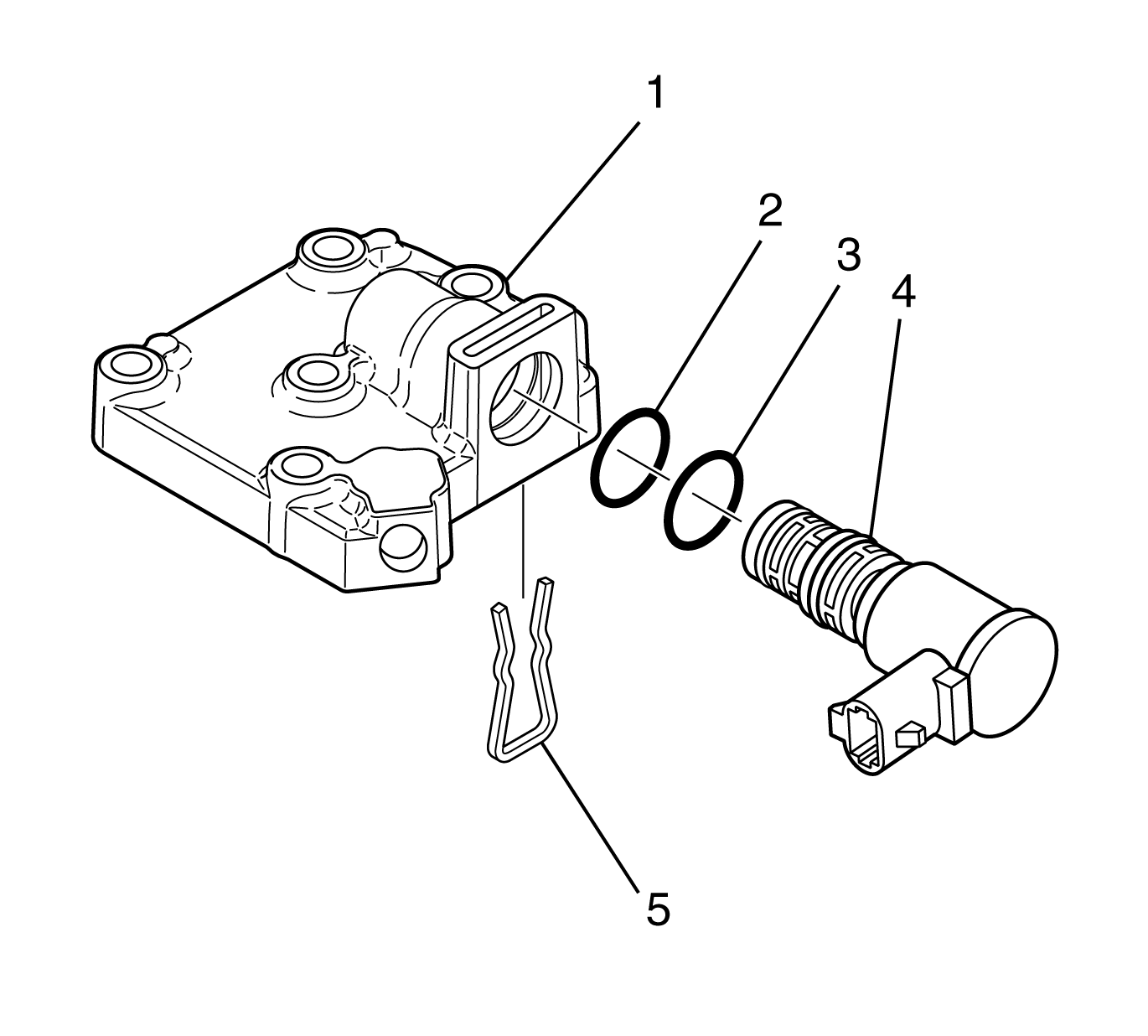
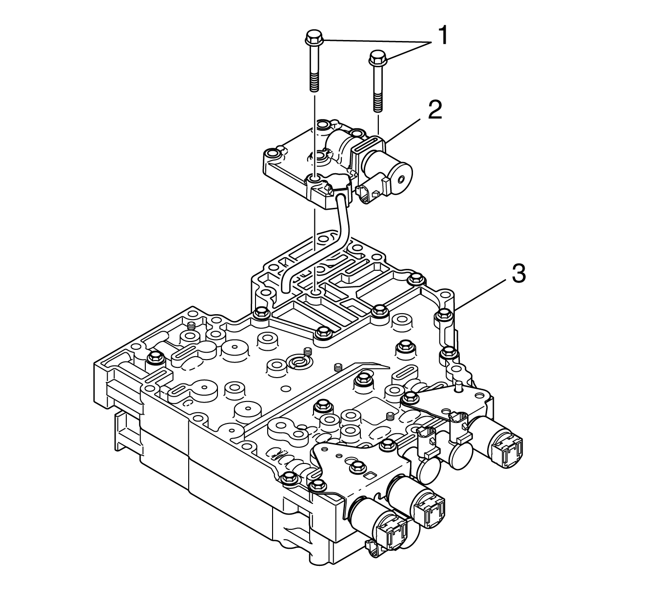
Important: The M6xl.0x65 modulated main pressure valve body retaining bolts are slightly longer and gold in color.
Tighten
Tighten the bolts to 12 N·m (108 lb in).
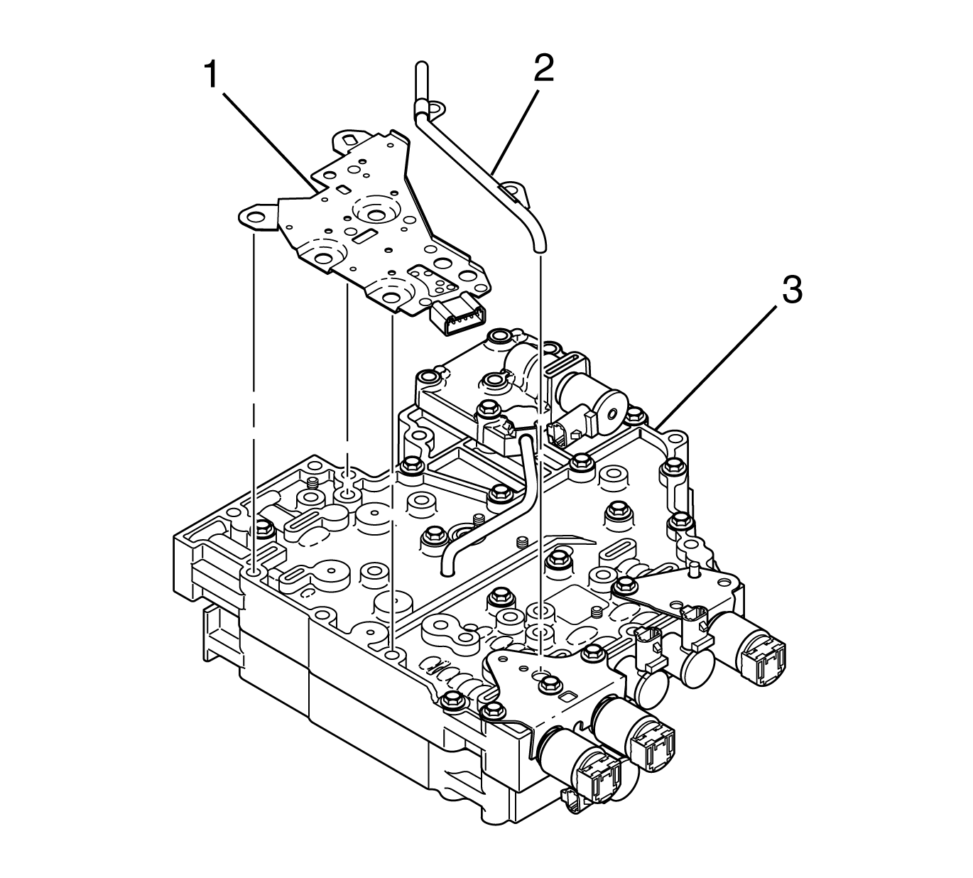
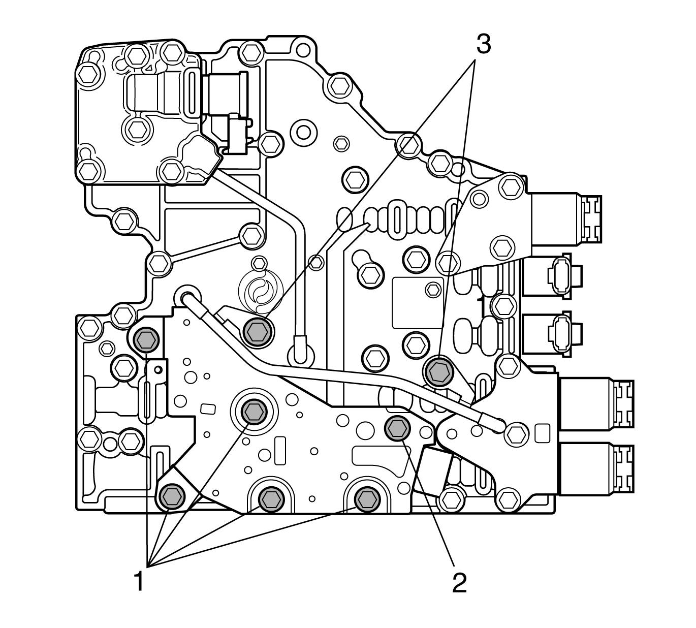
Important: Eight bolts retain the reverse signal pipe and the TFP switch.
• The TFP switch is retained by five bolts (1) and by one bolt (2). • Bolt (2) is slightly longer than the other five TFP switch retaining bolts (1). • The reverse signal pipe is retained by two bolts (3).
Tighten
Tighten the bolts to 12 N·m (108 lb in).
Tighten
Tighten the bolts to 12 N·m (108 lb in).
Special Tools
| • | J 33163 Valve Tray Set |
| • | J 43773 Valve Spring Compressor |
- Position main valve body assembly (4) on the work table so that the worm-track side is up.
- Align separator plate (2) with main valve body locating pins (3).
- Install separator plate (2).
- Align shift valve body assembly (1) with main valve body locating pins (3).
- Install the shift valve body assembly onto the separator plate.
- Position the control valve assembly on the work table so that the main valve body is facing up.
- Install 11 bolts (1) retaining the valve bodies together.
- Position the control valve assembly on the work table so that the shift valve body is up.
- Install the solenoid O-ring (4) onto the SS1 (5).
- Install the solenoid O-ring (3) onto the SS1 (5).
- Align the SS1 (5) so that the electrical connector points away from the nearest locating pin and is parallel to the separator plate as shown.
- Install the solenoid retainer (2).
- Position the control valve assembly on the work table so that main valve body (16) is facing up.
- Install the solenoid O-ring (14) onto the PCS1 (15).
- Install the solenoid O-ring (8) onto the PCS2 (9).
- Install the spring (10) , PCS1 trim valve (11), spring (12), and trim gain valve (13).
- Install the spring (5), PCS2 trim valve (6) and trim gain valve (7).
- Install PCS1 (15) so that the electrical connection faces up. Do not seat the solenoid.
- Install PCS2 (9) so the electrical connection faces up. Do not seat the solenoid.
- Align 2 accumulator plugs (3) so that the spring bores face up.
- Install 2 accumulator plugs (3) and 2 accumulator springs (2).
- Push PCS1 and PCS2 into the bores until the solenoids seat.
- Align the PCS retaining bracket (1) with main valve body locating pin (4).
- Install the PCS retaining bracket (1) so that PCS1 and PCS2, the accumulator plugs, and the accumulator springs are retained against the valve body.
- Install 3 bolts (1) retaining the PCS retaining bracket (2).
- Install the solenoid O-ring (3) onto the SS3 (4).
- Install the solenoid O-ring (2) onto the SS3 (4).
- Install the SS3 (4) so that the electrical connection faces up. seat the solenoid.
- Install the solenoid retainer (1).
- Install the solenoid O-ring (3) onto the SS2 (4).
- Install the solenoid O-ring (2) onto the SS2 (4).
- Install the SS2 (4) so that the electrical connection faces up. seat the solenoid.
- Install the solenoid retainer (1).
- Install the solenoid O-ring (6) onto the TCC PCS (7).
- Install the solenoid O-ring (5) onto the TCC PCS (7).
- Install the TCC PCS spring (3).
- Install the TCC PCS valve (4)
- Align the TCC PCS (7) so that the electrical connection faces up.
- Install the TCC PCS. Seat the solenoid.
- Align the PCS retaining bracket (2) with the main valve body locating pin.
- Install the PCS retaining bracket (2) so that the TCC PCS is against the valve body.
- Install the bolt (1) retaining the PCS retaining bracket (2).
- Install the O-rings (3 and 4) onto the MAIN MOD solenoid (6).
- Install the MAIN MOD solenoid (6).
- Install the MAIN MOD solenoid retainer (5) into the bottom of the valve body.
- Install the MAIN MOD solenoid body assembly (2).
- Install the 2 bolts (1) retaining the MAIN MOD solenoid valve body and the shift valve body to the main valve body.
- Align the bolts holes and alignment tabs of the transmission fluid pressure (TFP) switch (1) with the TFP switch holes in main valve body (3).
- Install TFP switch (1) onto main valve body (3).
- Install five bolts (1) and one bolt (2) retaining the TFP switch to the main valve body.
- Install the reverse signal pipe (2) onto the main valve body.
- Install two bolts (3) retaining the reverse signal pipe and the shift valve body to the main valve body.
Notice: Use the correct fastener in the correct location. Replacement fasteners must be the correct part number for that application. Fasteners requiring replacement or fasteners requiring the use of thread locking compound or sealant are identified in the service procedure. Do not use paints, lubricants, or corrosion inhibitors on fasteners or fastener joint surfaces unless specified. These coatings affect fastener torque and joint clamping force and may damage the fastener. Use the correct tightening sequence and specifications when installing fasteners in order to avoid damage to parts and systems.
Tighten
Tighten the bolts to 12 N·m (108 lb in).
Important:
• O-ring (4) is slightly larger than O-ring (3). • P/N 29536833 is printed on the shift solenoid 1 (SS1) (5).
Important: P/N 29541895 is printed on the pressure control solenoid 1 (PCS1).
Important: P/N 29541896 is printed on the pressure control solenoid 2 (PCS2).
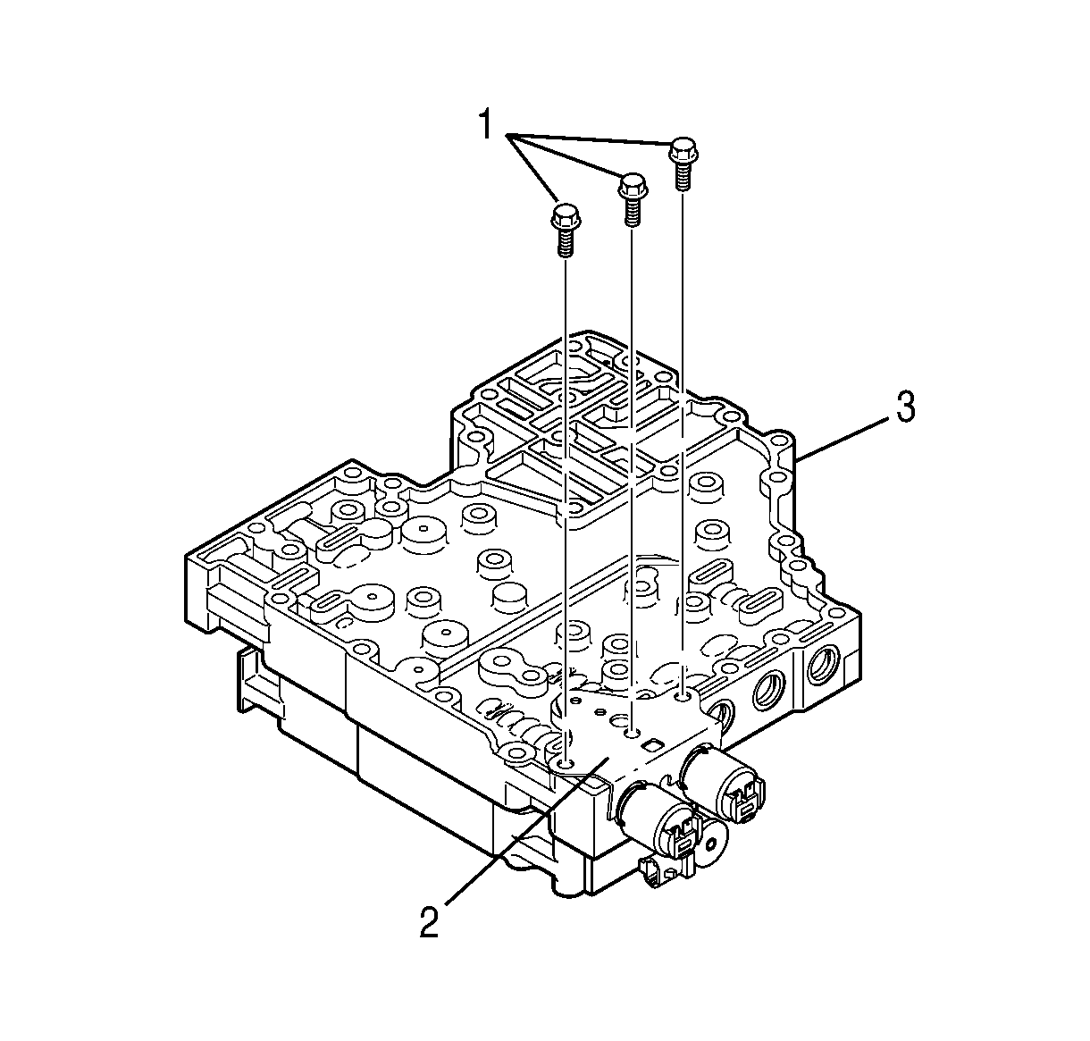
Tighten
Tighten bolts (1) to 12 N·m (108 lb in).
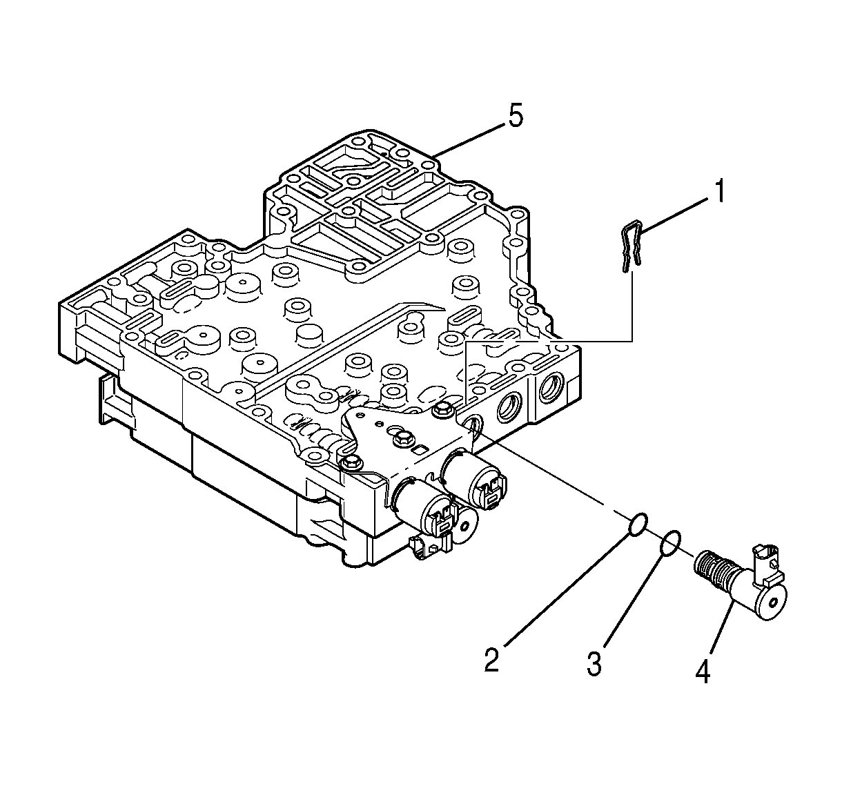
Important:
• The solenoid O-rings are brown. • O-ring (3) is slightly larger than O-ring (2). • P/N 29536833 is printed on the shift solenoid 3 (SS3).
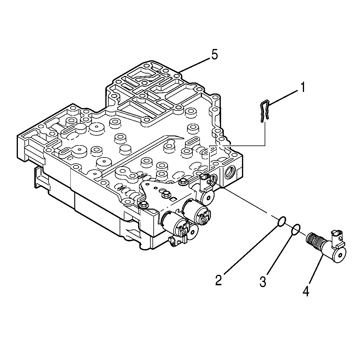
Important:
• The solenoid O-rings are brown. • O-ring (3) is slightly larger than O-ring (2). • P/N 29536833 is printed on shift solenoid 2 (SS2).

Important:
• P/N 29541898 is printed on the torque converter clutch pressure control solenoid (TCC PCS). • The solenoid O-rings are green. • O-ring (6) is slightly larger than O-ring (5).
Tighten
Tighten the bolt to 12 N·m (108 lb in).
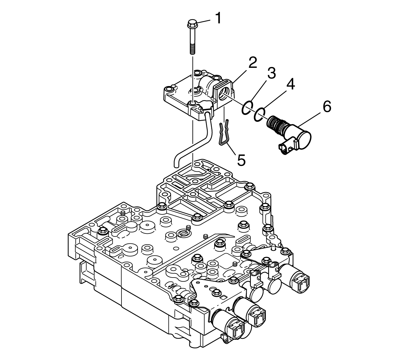
Important:
• The solenoid O-rings are brown. • O-ring (3) is slightly larger than O-ring (2) • P/N 29536833 is printed on the modulated main pressure (MAIN MOD) solenoid.
Important: Four bolts pass through the MAIN MOD solenoid valve body to retain the control valve body assembly to the transmission case. Install these bolts when installing the control valve body assembly.
Tighten
Tighten bolts to 12 N·m (108 lb in).


Important:
• Bolt (2) is slightly longer than the other bolts (1). • The TFP switch is retained by five bolts (1) and by bolt (2).
Tighten
Tighten the bolts to 12 N·m (108 lb in).
Tighten
Tighten the bolts to 12 N·m (108 lb in).
