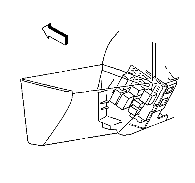
For 1990-2009 cars only
Removal Procedure
- Remove the left side end panel.
- Remove the knee bolster. Refer to Knee Bolster Replacement in Instrument Panel, Gages and Console.
- Disconnect all the wiring connectors from the fuse block.
- Remove all the fuses.
- Remove the turn signal relay from the back of the fuse block.
- From behind the fuse block, remove the retaining bolt.
- Insert a screw driver between the fuse block and the wire harness block to separate.
- Push on the retainers in order to remove the fuse block.
- Remove the fuse block from the vehicle.

Installation Procedure
- Install the fuse block onto the I/P assembly until it clicks in place.
- Install the wire harness block to the back of the fuse block.
- Install the bolt.
- Install the turn signal relay to the back of the fuse block.
- Using the wiring diagram on the cover of the fuse panel, install the fuses.
- Install the electrical connectors.
- Install the knee bolster. Refer to Knee Bolster Replacement in Instrument Panel, Gages and Console.
- Install the left side end panel.
Notice: Refer to Fastener Notice in the Preface section.
Tighten
Tighten the bolt to 6 N·m (53 lb in).

