VIBRATION AT 1500-2500 RPM DIAGNOSTIC AND REPAIR STEPS

MODELS: 1985-86 Cl AND C2 TRUCKS WITH THE 4.3L V6 ENGINE AND THM 400 TRANSMISSION
Some 1985-86 C1 and C2 trucks with the 4.3L V6 may experience a vehicle vibration in the 1500-2500 rpm range. This condition may be the result of the natural frequency second order vibration of the 4.3L V6 engine which is then amplified by the other powertrain components such as the transmission, transmission crossmember, and the center support bearing crossmember for the two-piece propshaft. Vehicles exhibiting this condition can be repaired by using the following procedure:
Procedure
1. Road test the truck to verify the complaint.
2. Inspect the truck to make sure no components are loose or grounding out against the frame such as the exhaust system, hoses, and lines, etc.
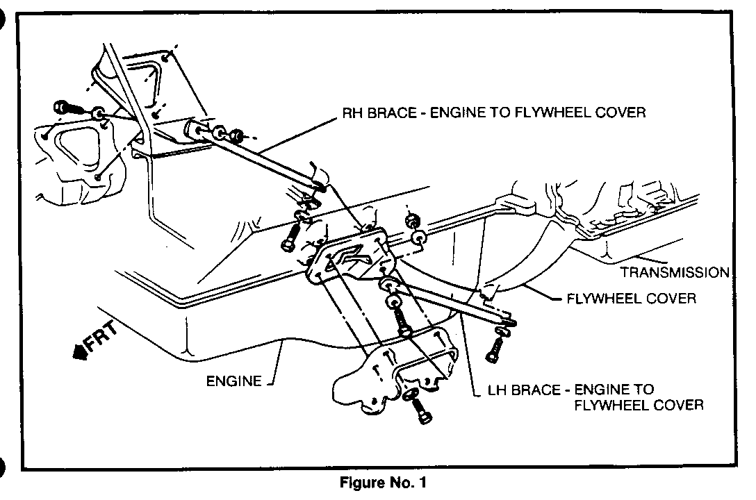
3. Check vehicle to make sure engine to transmission strut bars are on the vehicle, see Figure No. 1. If strut bars are missing, they must be installed. Refer to section 0.00 page 0-26, of the C/K parts book illustrations for part numbers.
4. Re-index the torque converter to try to reduce the vibration.
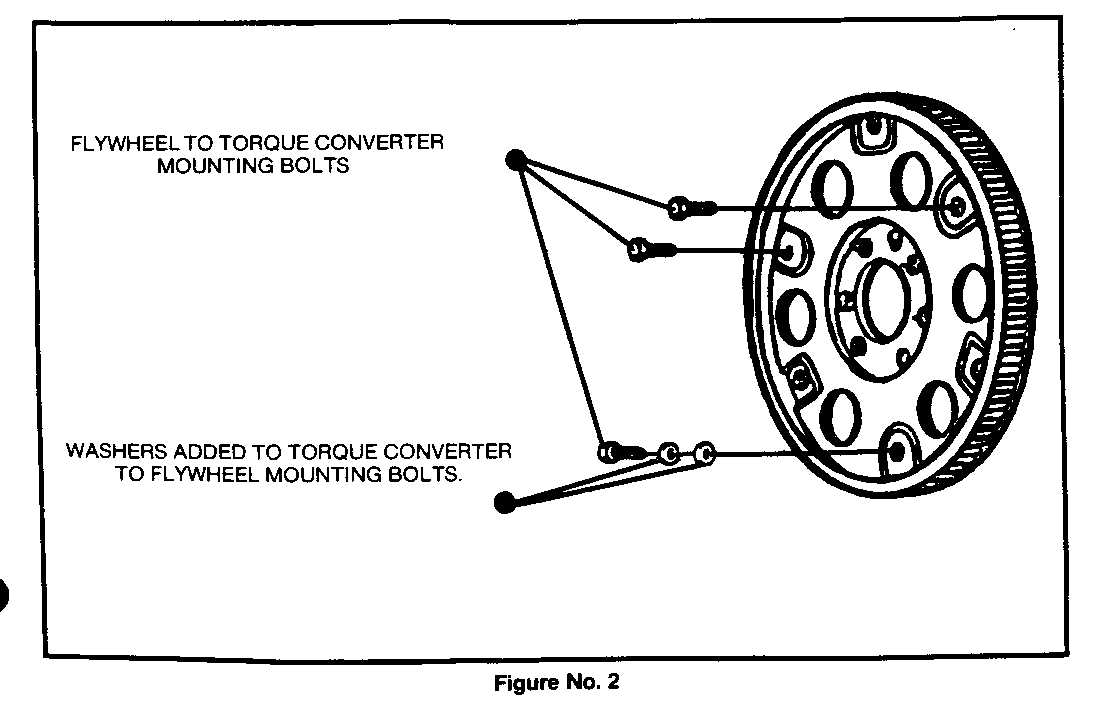
5. If re-indexing the torque converter does not affect the vibration, remove one of the torque converter to flywheel mounting bolts and install two flat washers (M10 x 3mm thick) between the bolt head and the flywheel and retorque to 57-65 Nm (42-50 lb ft) as per instructions in Figure No. 2. Retest the engine for the vibraton. Use this test on all three converter bolt locations, one bolt at a time, to reduce the vibration. If adding washers to the torque converter bolts does not correct the vibration, remove the washers and torque the bolts to 57-65 Nm (42-50 lb ft). If adding washers to the torque converter bolts corrects the vibration, the washers can be left attached to the bolt, but the bolt must be installed using GM thread locking compound P/N 1052624 and torqued to 57-65 Nm (42-50 lb ft).
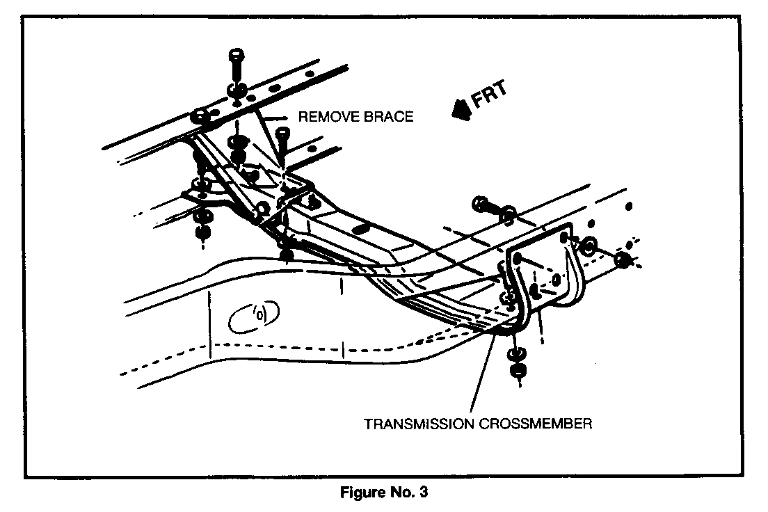
6. If the procedure outlined in step 4 does not correct the vibration, raise the truck and remove the transmission crossmember support brace, see Figure No. 3.
NOTE: STEP #7 CAN ONLY BE DONE IF THE STRUT BARS ARE IN PLACE. THE STRUT BARS ARE NECESSARY TO MAINTAIN STRUCTURAL INTEGRITY BETWEEN THE ENGINE AND TRANSMISSION.
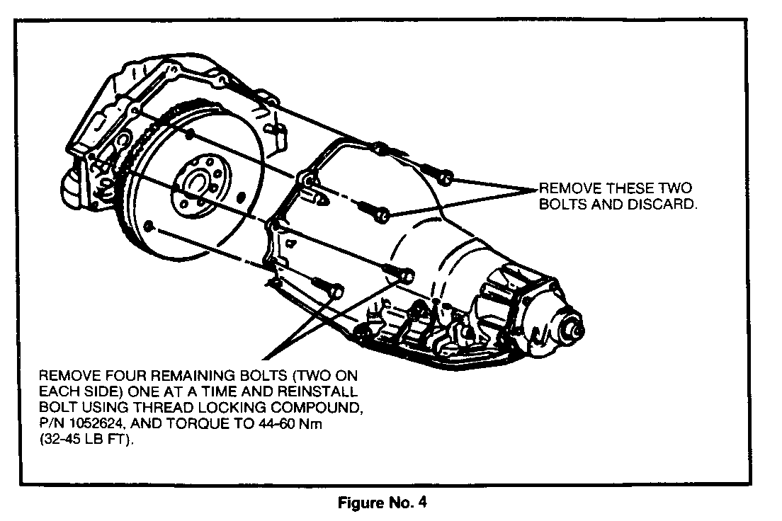
7. Remove the two upper transmission to engine mounting bolts and discard. Remove the four remaining transmission to engine mounting bolts, one at a time, and apply one drop of thread locking compound P/N 1052624 to the thread and reinstall the bolts and torque to 44- 60 Nm (32-45 lb ft).
NOTE: If one of the upper transmission to engine mounting bolts has a ground strap attached to it, it will have to be attached to another bolt on the engine. Make sure that all dirt/corrosion or paint is removed from the mounting surface to assure a good ground contact. See Figure No. 4.
8. Retest the vehicle.


General Motors bulletins are intended for use by professional technicians, not a "do-it-yourselfer". They are written to inform those technicians of conditions that may occur on some vehicles, or to provide information that could assist in the proper service of a vehicle. Properly trained technicians have the equipment, tools, safety instructions and know-how to do a job properly and safely. If a condition is described, do not assume that the bulletin applies to your vehicle, or that your vehicle will have that condition. See a General Motors dealer servicing your brand of General Motors vehicle for information on whether your vehicle may benefit from the information.
