SERVICE AND PARTS INFORMATION 700R4 WITH/W/O AUX VALVE BODY

Bulletin Covers:
A 1987 model THM 700-R4 transmission may be built with or without an auxiliary control valve assembly (AUX V/B). Identification, service procedures, new parts and fluid passage information for this change are provided in this bulletin.
IMPORTANT: 1987 GM Service Parts Catalogue printed in September, 1986 gives information for a 1987 transmission built with an AUX V/B. Use of this printed information on a transmission built without an AUX V/B can create a misbuild.
Additionally, other changes to the 1987 THM 700-R4 transmission that affect service procedures and/or new part information are also included.
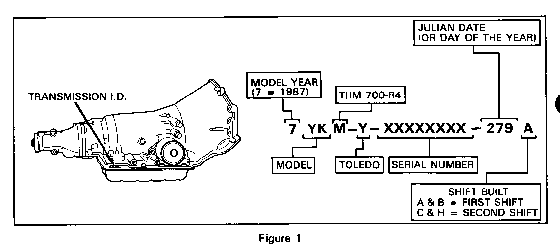
Date Of Changes: (Figure 1) ---------------
By October 6, 1986, (Julian Date279) all 1987 THM 700-R4 transmission models were built with the AUX V/B. Also, all 1987 Service Replacement Transmission Assembly (SRTA) models are built with the AUX V/B.
Service Action:
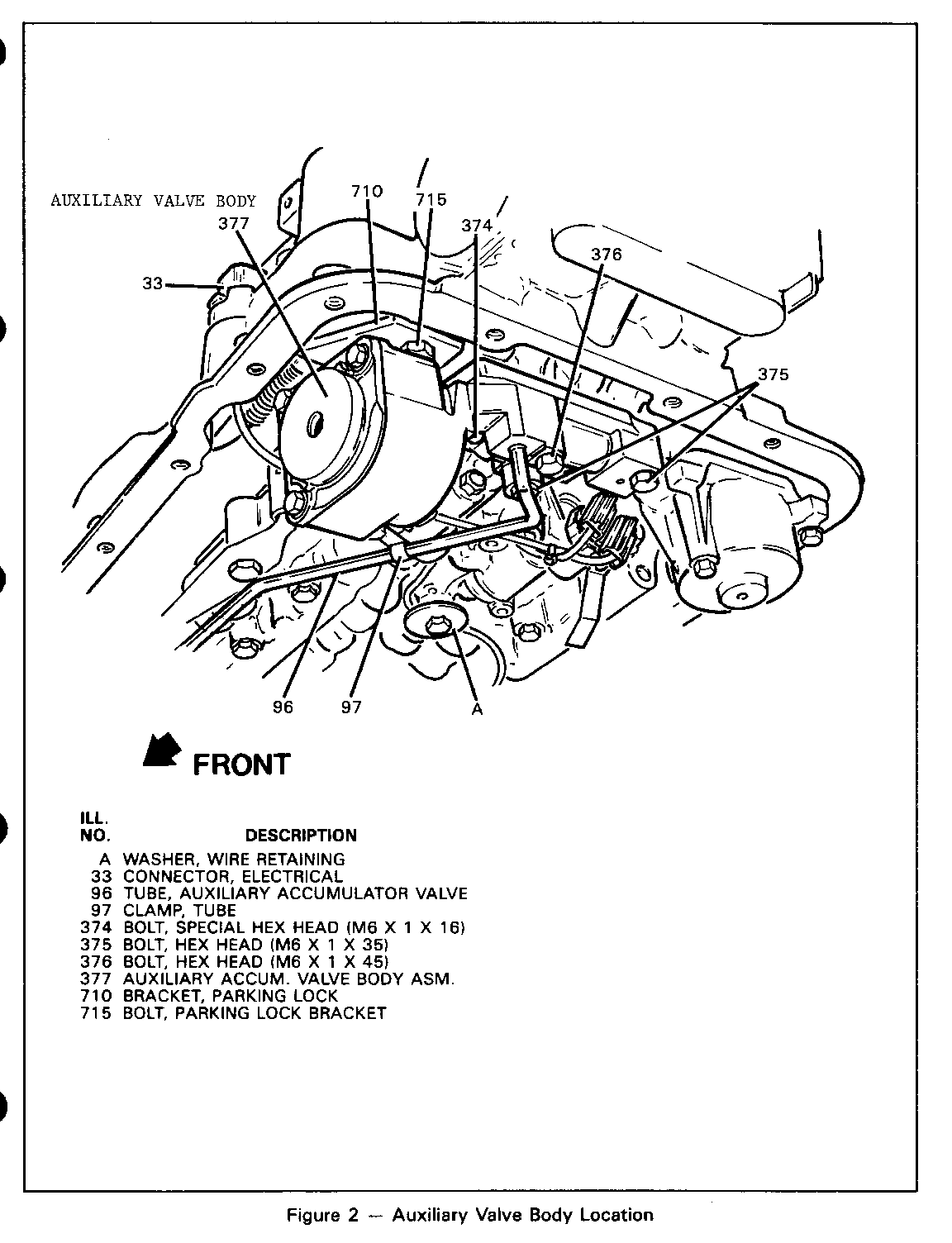
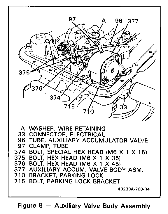
To determine which service procedures and parts to use on a 1987 THM 700-R4 assembly with a Julian Date between 198 and 279, remove the transmission oil pan and look for an auxiliary valve body (refer to Figure 2).
Service Parts Information:
If the auxiliary valve body is present, refer to 1987 GM Parts Catalogue Listing dated November, 1986.
If the auxiliary valve body is not present, refer to the February 1987 Parts Catalogue Revision (If this information is not available, contact the NPN Department at your Servicing PDC).
Service Manual Reference:
1987 Service Manual procedures and illustrations in manuals printed prior to November, 1986 may not include information provided in this bulletin.
SUMMARY OF BULLETIN INFORMATION
BEFORE AFTER DATE OF DATE OF SUBJECT CHANGE CHANGE ------- ------- -------
Auxiliary Control Valve Assembly Not Used Used --turbine shaft seals Scarf Cut Solid
Fluid Passage Identification ------ ------
Oil Pump Assembly 7 Vane 10 Vane Plugged Hole Add Feed Pipe
Forward Clutch Assembly Stack Up: Stack Up: thick spacer no spacer & thin apply or thin apply narrow sprag: wider sprag: wear plate no wear plate thrust washer no thrust washer
Lo And Reverse Roller Clutch Used Pre-SOP Wider Roller 1987 Models Elements
Oil Pan Round Magnet Square Magnet Dimpled Pan Deeper Pan
Temperature Switch Not Used SOP Some Models
TRANSMISSION APPLICATIONS: SUBJECT:
1987 THM 700-R4 (MD8) New Auxiliary Valve Body Assembly
TRANSMISSION MODELS:
All Models
Change To Assembly Components:
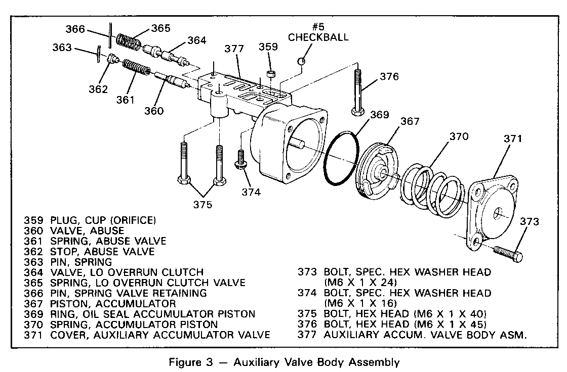
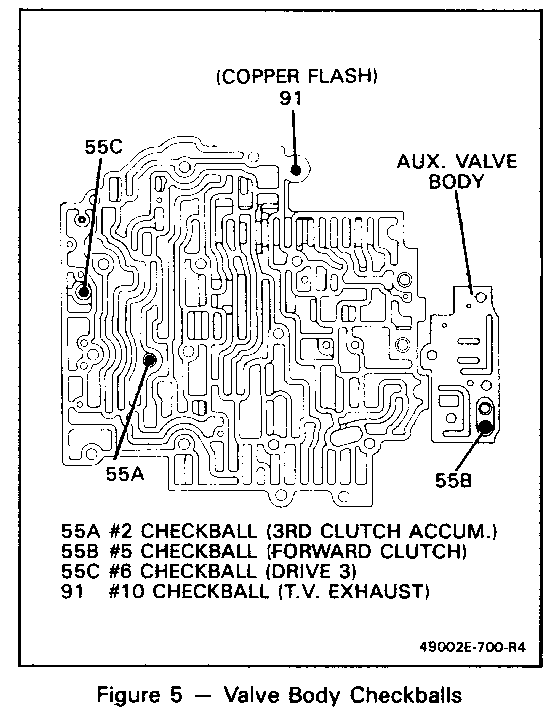
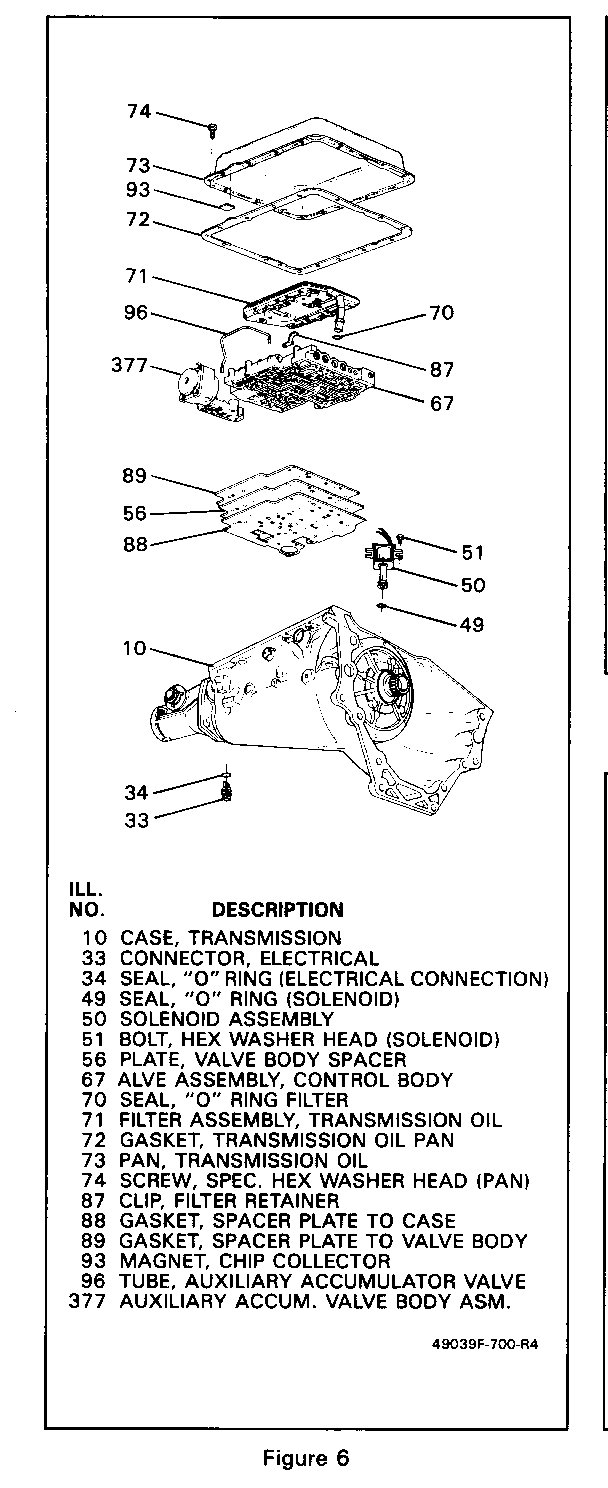
o New auxiliary valve body assembly with the following components (Figure 3 & 6): --lo overrun clutch valve (364) and spring (365) --abuse valve (360) and spring (361) --orificed cup plug (359) --accumulator piston (367) and spring (370) --#5 checkball (used in the valve body on 1982 through early 1987 models, Figures 3 & 5) --tube (96) from pump cover to auxiliary valve body (Figures 6 & 8)
Major Components Changed With Addition Of New Auxiliary Valve Body Assembly:
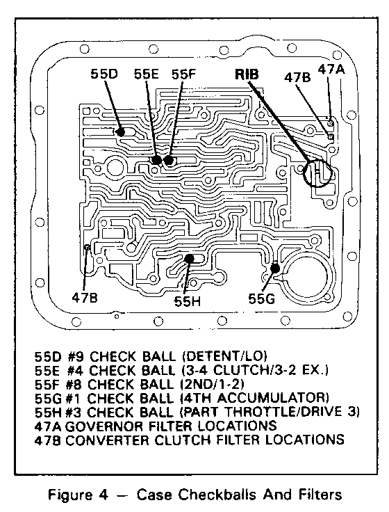
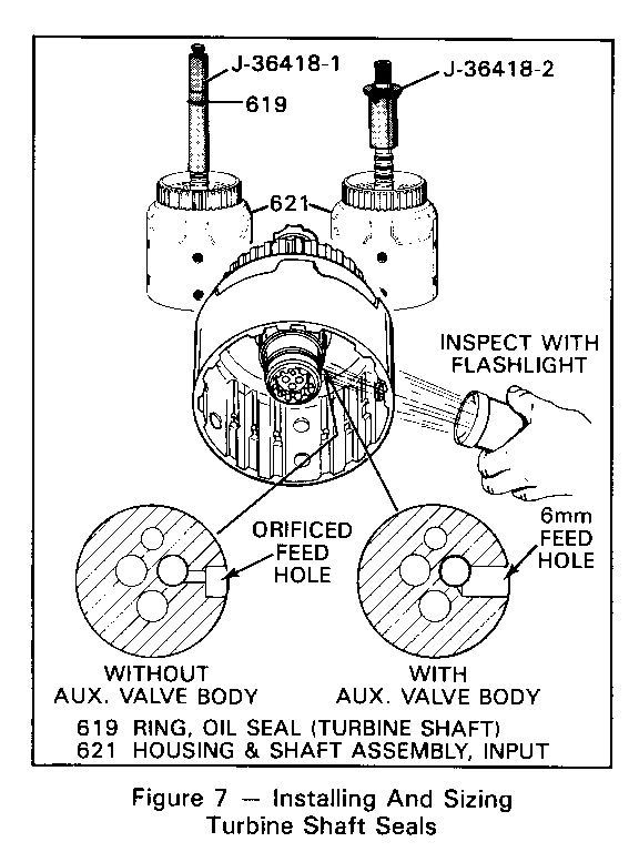
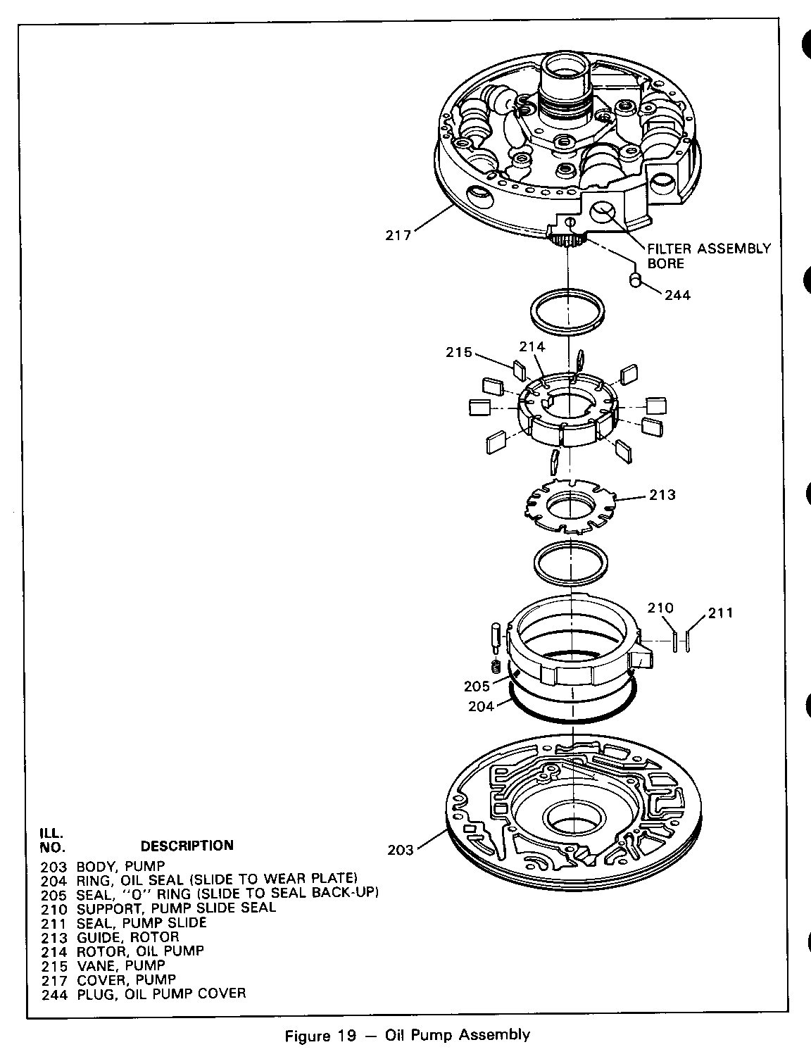
a Cup plug (244) eliminated from pump cover (Figure 19) --tube (96) is used in this bore o New input housing assembly (621) with solid turbine shaft seals (619) (Figure 7) --scarf cut seals MUST NOT be used in place of solid seals --6mm forward clutch feed hole in turbine shaft (Figure 7) o New spacer plate (56) and gaskets (88 & 89) (Figure 6) o New case assembly (10) (Figure 6) --rib added to lo/reverse passage under auxiliary valve body (Figure 4) --new orificed lube hole near governor bore in case o New control valve assembly (67) (Figure 6) --not interchangeable on transmissions without an auxiliary valve body
Date Of Change
October 6, 1986, Julian Date 279, for all 1987 THM 700-R4 transmission models. All 1987 Service Replacement Transmission Assemblies (SRTA) models have the new auxiliary valve body assembly.
Service Action:
IMPORTANT: THE "MAJOR COMPONENTS CHANGED" LISTED ON PAGE 3 CANNOT BE USED TO SERVICE 1982 THROUGH 1987 TRANSMISSIONS THAT DO NOT HAVE AN AUXILIARY VALVE BODY.
o When using a new pump cover (217, Figure 19) for a transmission with an auxiliary valve body, cup plug (244) must be removed. (Refer to "New Oil Pump Assembly" section in this Bulletin.)
o When replacing a case assembly on a 1987 transmission, inspect the new case for a rib in the lo/reverse passage (Figure 4).
--if rib is present: use only on models with an auxiliary valve body
o When servicing the turbine shaft seals (619) do not use scarf cut seals on a transmission with an auxiliary valve body. (See "Service Parts" section below).
--Use installation tool (J 36418-1) and sizing tool (J36418-2) for solid turbine shaft seals (Figure 7)
o Input housing and shaft assemblies (621) used on transmissions with an auxiliary valve body are not interchangeable with previous model year transmissions.
Service Parts
Four input housing and turbine shaft assemblies are available for 1987 model transmissions:
Part Number Description ----------- ----------- 8657901 -298mm turbine shaft and input housing with scarf cut seals (for a transmission without an auxiliary valve body)
8657902 -245mm turbine shaft and i.nput housing with scarf cut seals (for a transmission without an auxiliary valve body)
8657903 -245mm turbine shaft and input housing with solid , seals (for a transmission with an auxiliary valve body)
8657904 -298mm turbine shaft and input housing with solid seals (for a transmission with an auxiliary valve body)
Six transmission case assemblies are available for 1987 model transmissions:
Part Number Description ----------- ----------- *8648995 -Case Assembly Complete (for a transmission without an auxiliary/valve body)
*8648993 -Case Assembly Complete (for a transmission without an auxiliary valve body)
*8648994 -Case Assembly Complete (for a transmission without an auxiliary valve body)
*8648903 -Case Assembly Complete (for a transmission with an auxiliary valye body)
*8648904 -Case Assembly Complete (for a transmission with an auxiliary valve body)
*8648905 -Case Assembly Complete (for a transmission with an auxiliary valve body)
*SEE SERVICE PARTS LIST FOR MODEL APPLICATION
TRANSMISSION APPLICATIONS: SUBJECT:
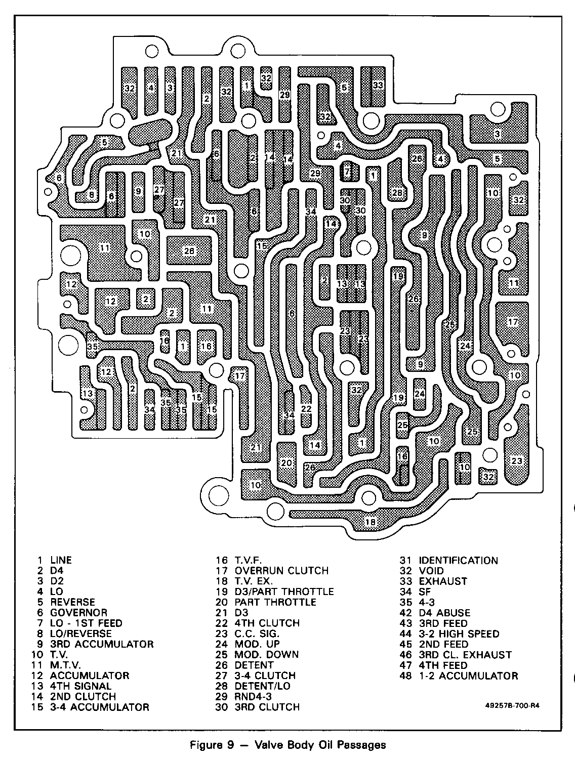
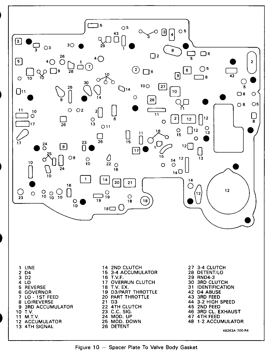
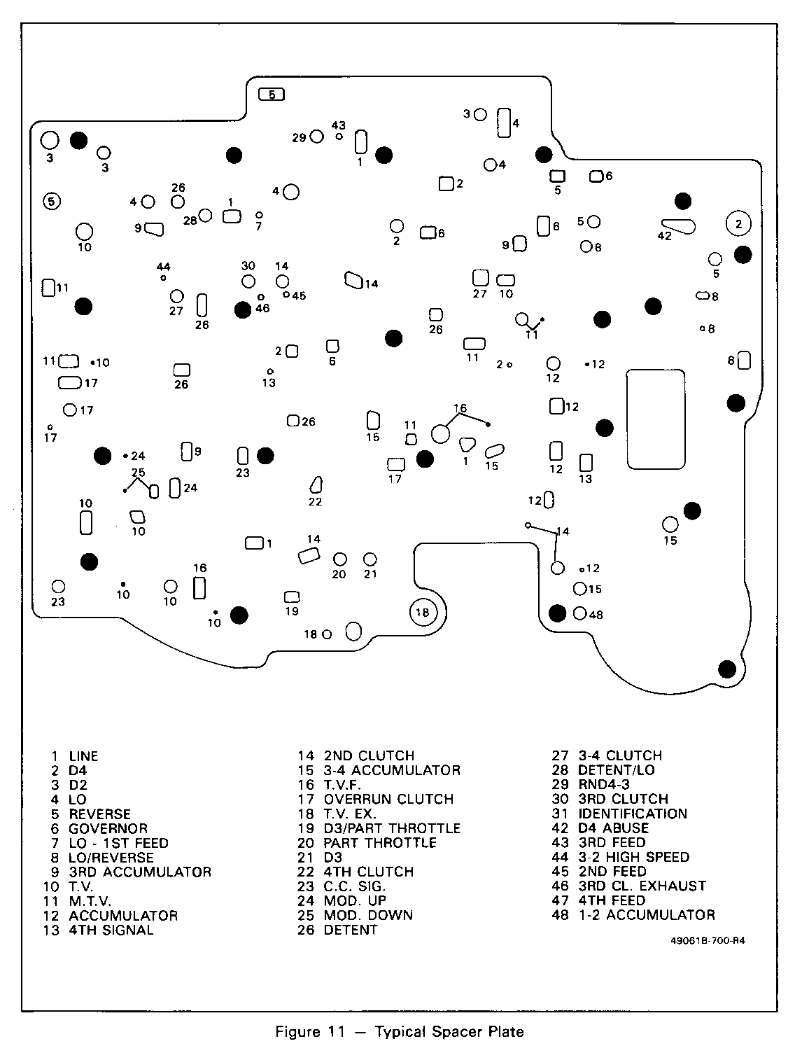
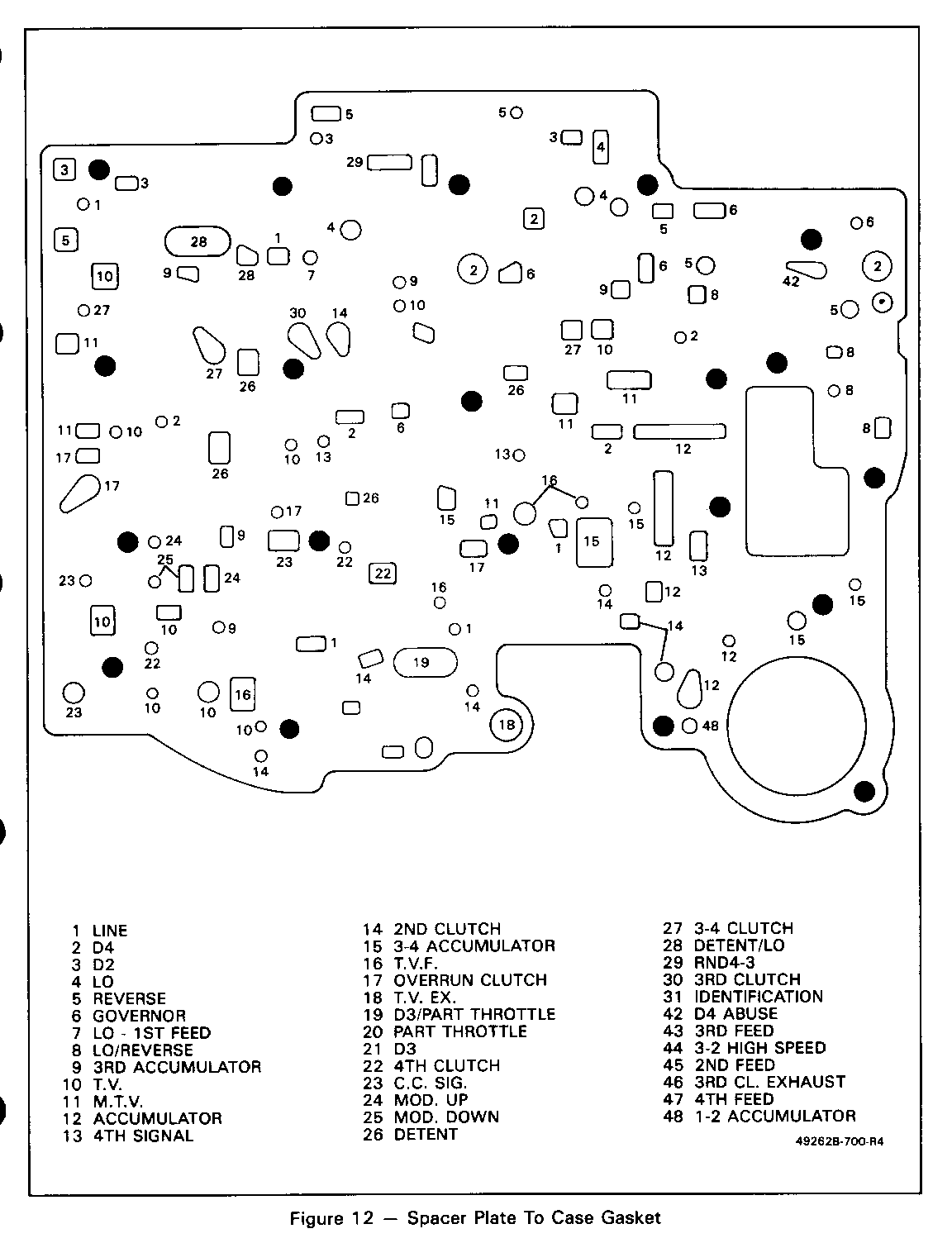
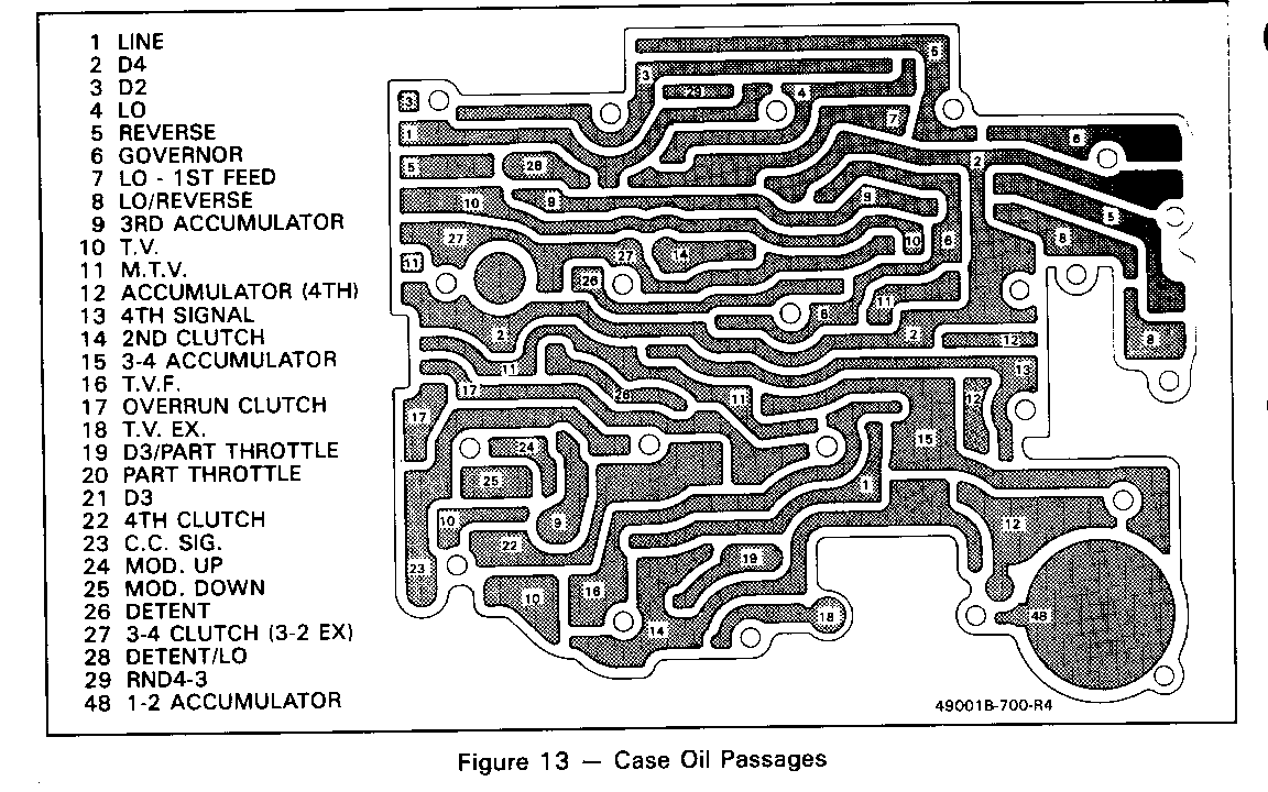
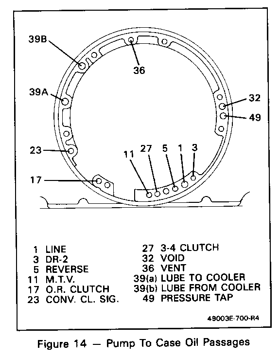
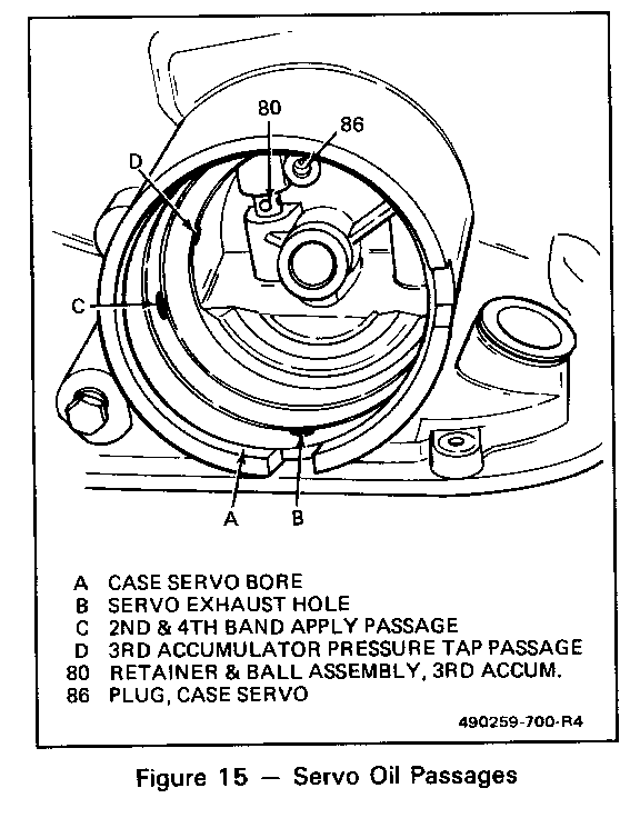
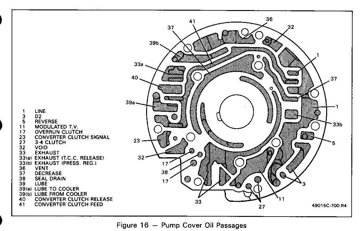
1987 THM 700-R4 (MD8) Fluid Passage Identification Changes
TRANSMISSION MODELS:
All Models With Auxiliary Valve Body
Change to Assembly Components:
Revised fluid passages in the following compohents:
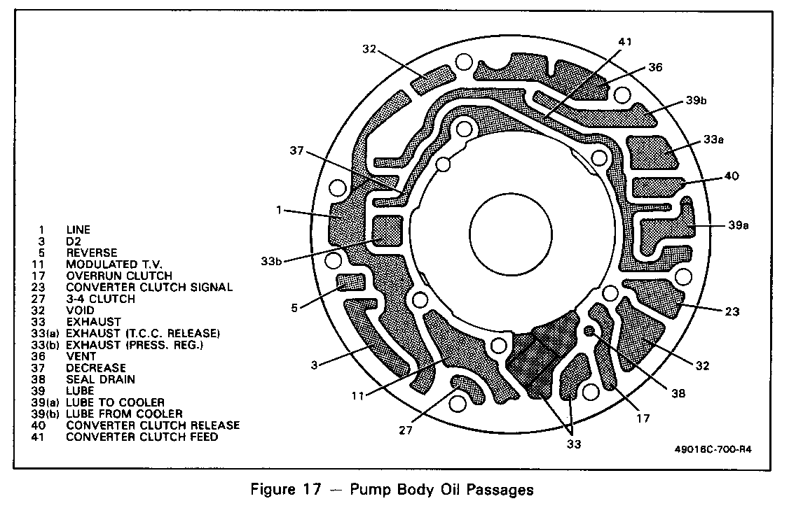
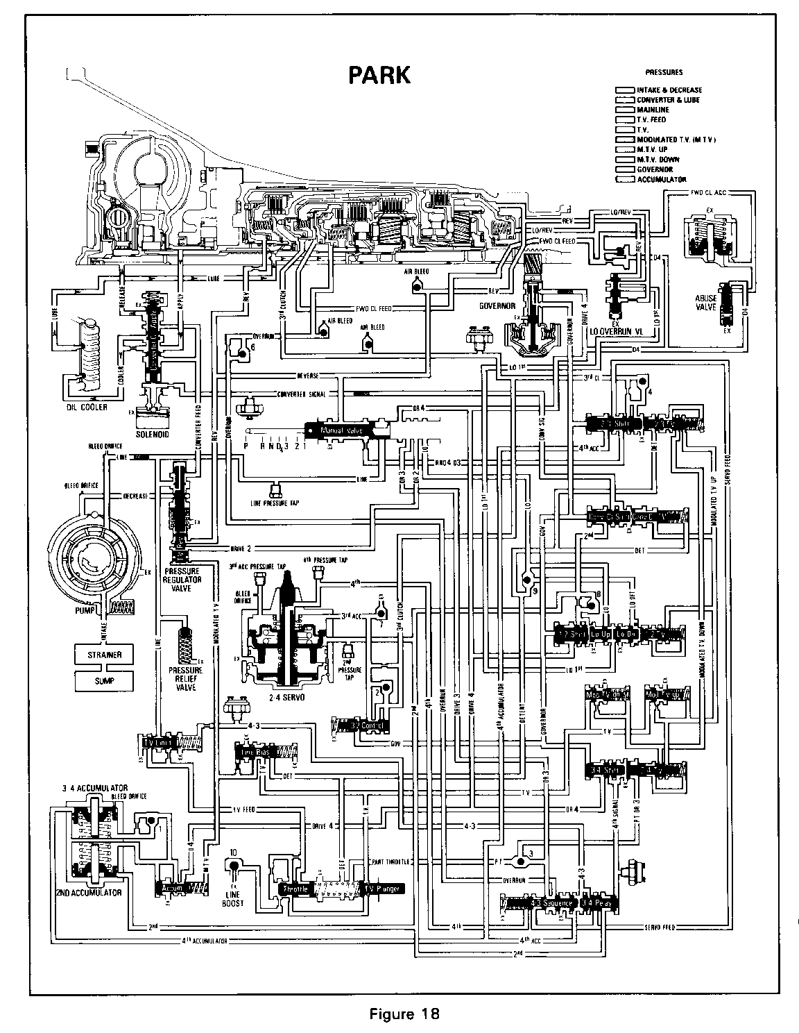
o Valve Body (Figure 9) o Spacer Plate to Valve Body Gasket (Figure 10) o Spacer Plate (Figure 11) o Spacer Plate to Case Gasket (Figure 12) o Case Oil Passages (Figure 13) o Pump to Case Oil Passages (Figure 14) o Servo Oil Passages (Figure 15) o Pump Cover Oil Passages (Figure 16) o Pump Body Oil Passages (Figure 17) o Hydraulic Schematic of "Park' (Figure 18)
Date Of Change:
October 6, 1986, Julian Date 279, for all 1987 THM 700-R4 transmission models. All 1987 Service Replacement Transmission Assemblies (SRTA) models have the new auxiliary valve body assembly.
Service Action:
Use illustrations provided in this bulletin for identifying/diagnosing a 1987 THM 700-R4 transmission without an auxiliary valve body.
TRANSMISSION APPLICATIONS: SUBJECT:
1987 THM 700-R4 (MD8) New Oil Pump Assembly
TRANSMISSION MODELS:
All Models
Change To Assembly Components:
o Increase of 3 pump vanes, from 7 to 10 vanes (215, Figure 19) o New oil pump rotor (214) and rotor guide (213) to accommodate additional vanes. o Elimination of cup plug (244) on models using an auxiliary valvebody assembly (see information contained in this Bulletin on page 3 "Major Component Changed" section).
Date Of Change:
October 28, 1986, Julian Date 301, for all 1987 THM 700-R4 transmission models. During the production of 1986 and early 1987 models, up to October 28, 1986, only some transmission assemblies used the 10 vane assembly. All 1987 Service Replacement Transmission Assemblies (SRTA) models have the new oil pump assembly.
Service Action:
When using the new pump cover (217) inspect for cup plug (244). Cup plug must be present for transmissions not using an auxiliary valve body. The cup plug should be removed for assembly of feed tube (96) on transmissions that use an auxiliary valve body.
Service Parts Information:
Part Number Description
8649964 Pump Body Assembly Complete (1985-1987 models)
8649951-8649955 Selective Vane Ring Packages (1987 models only)
8649950 Pump Body Assembly Complete (1985-1986 models) (These pump bodies are to be used until stock is depleted unless noise condition is exhibited)
Note:
The pump body and pump cover assemblies used on 1982 through 1984 transmission are NOT serviced separately.
TRANSMISSION APPLICATIONS: SUBJECT:
1987 THM 70OR-R4 (MD8) New Forward Clutch Assembly
TRANSMISSION MODELS:
All Models
Change To Assembly Components:
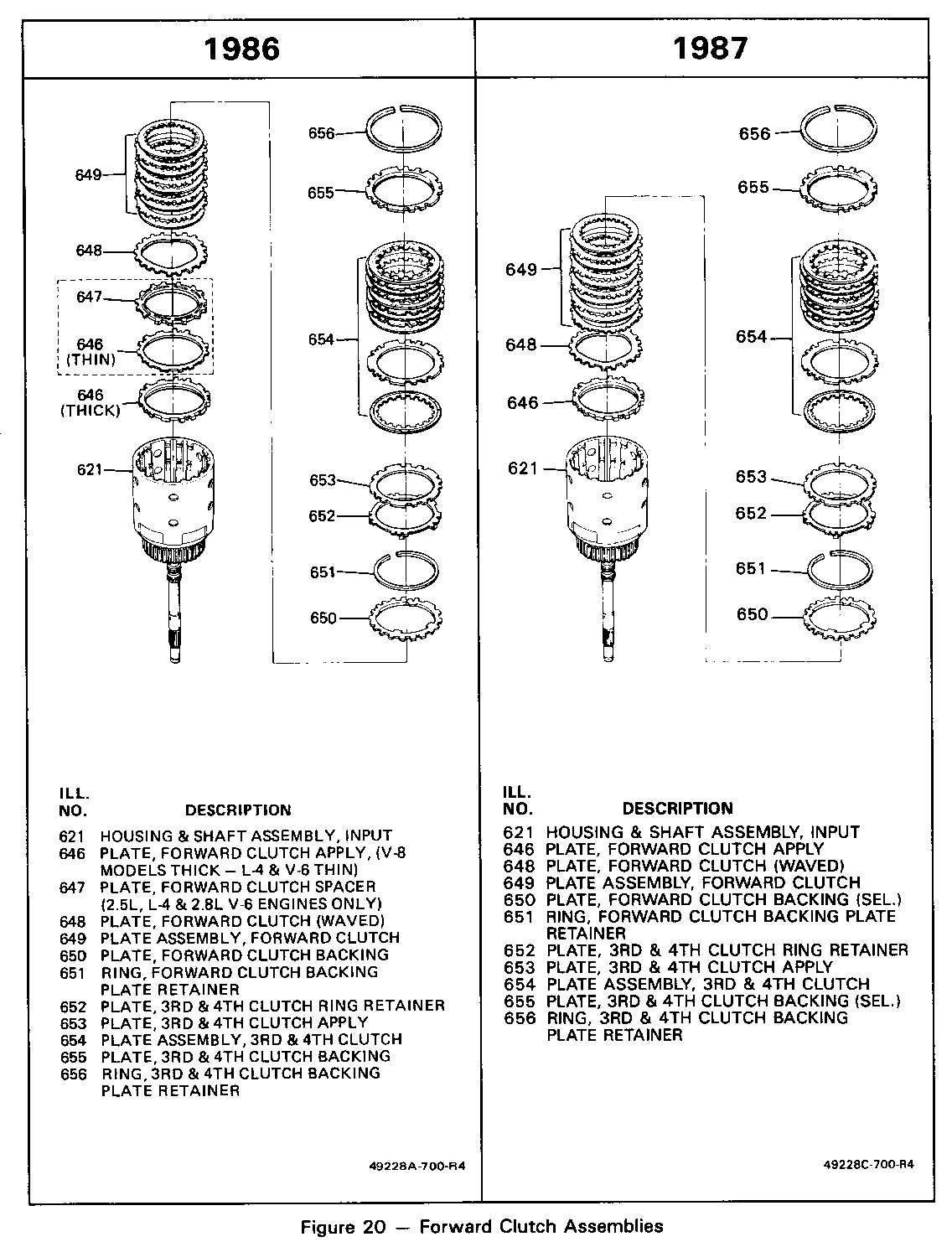
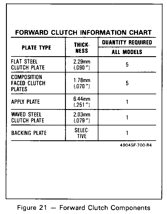
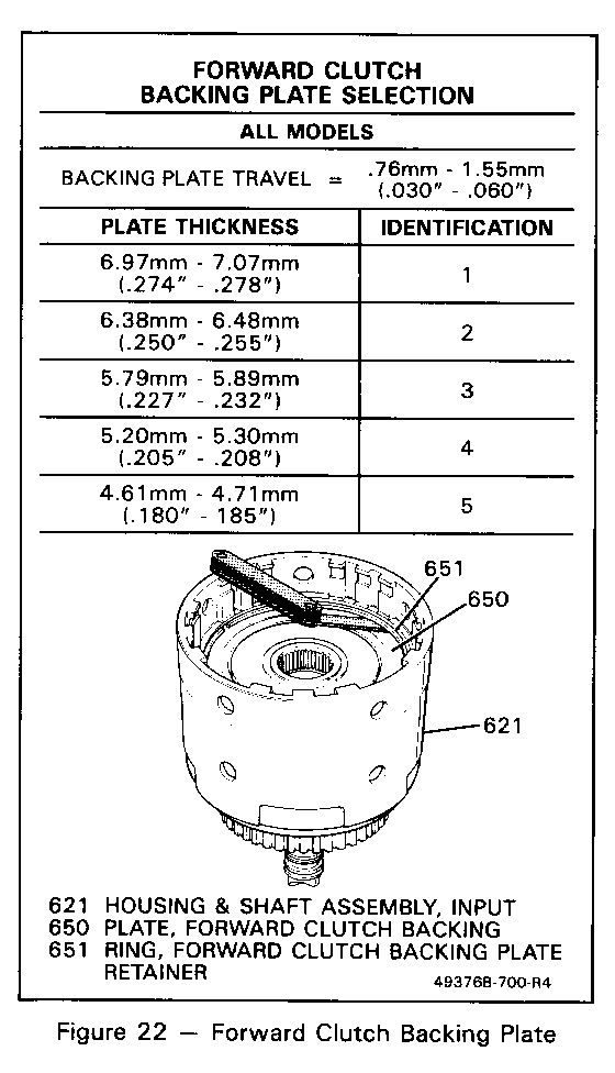
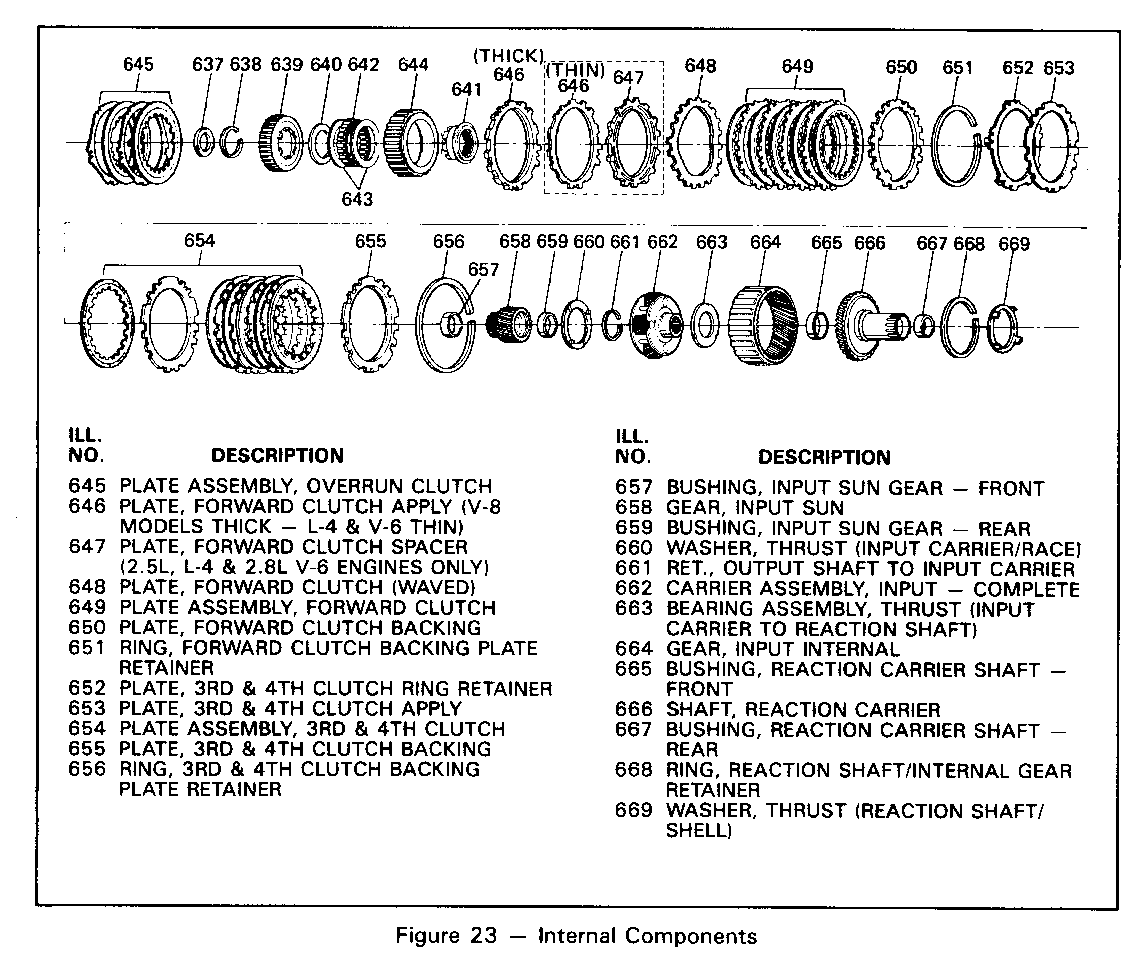
o New clutch plate stack up for all models (Figures 20 & 21) --5 steel plates (649) --5 composition plates (649) --l apply plate (646) --l waved steel plate (648) --1 selective backing plate (650, Figures 21 & 22)
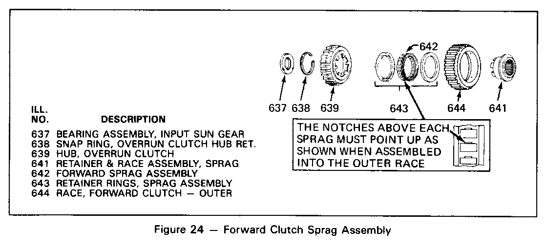
o New forward clutch sprag assembly (Figures 23 & 24) --increase of 2 elements (total of 28 elements) --larger inside diameter of sprag outer race (644) --larger outside diameter of sprag retainer and race assembly (641) --new retainer rings (643) for sprag elements
o New overrun clutch hub (639) due to elimination of: --sprag assembly wear plate (640) --thrust washer (input carrier/sprag) (660)
Date Of Change:
July 17, 1986, Julian Date 198, for all 1987 THM 700-R4 transmission models. All 1987 Service Replacement Transmission Assemblies (SRTA) models have the new forward clutch assembly.
Service Action:
When using the new sprag, race, and hub assembly on 1982 through 1986 THM 700-R4 transmiss4ons, the sprag assembly wear plate (640) and input carrier to race thrust washer (660) must be removed and not used.
NOTE: If transmission has AUX V/B, solid turbine shaft seals must be used.
Service Parts Information:
Part Number Description
8663773 Sprag, Race and Hub Assembly (1987 YAM, YCM, YDM, YMM, YSM, YWM, YZM, models only)
8663774 Sprag, Race and Hub Assembly (All other 1987 models)
TRANSMISSION APPLICATIONS: SUBJECT:
1987 THM 700-R4 (MDB) New Lo And Reverse bollet Clutch Assembly . TRANSMISSION MODELS:
All Models
Change To Assembly Components
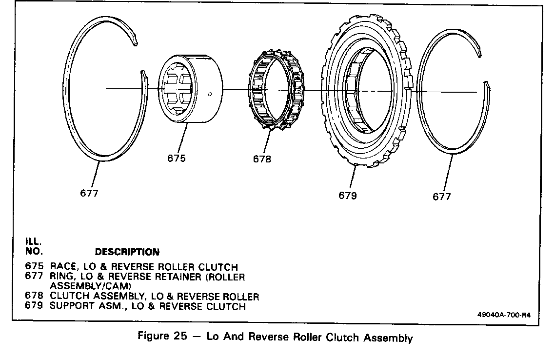
o .150" (3.81mm) wider roller elements for assembly (678, Figure 25)
Date Of Change:
June 19, 1986, Julian Date 170 for late 1986 model year production transmissions. All 1987 production and Service Replacement Transmission Assembly (SRTA) models have the new 10 and reverse roller clutch assembly.
Service Action:
When servicing a lo and reverse roller clutch on a 1986 or 1987 model transmission only use the new service kit assembly 8663094. Components 675, 677, 678 and 679 (Figure 25) were serviced individually for all 1982 through 1985 model transmissions. Do not use these individual components (included in service kit 8663094) to service a 1986 or 1987 model transmission. Service Parts Information:
Part Number Description
8663094 Lo and Reverse Roller Clutch and Support Assembly (1982-1987 models)
TRANSMISSION APPLICATION: SUBJECT:
1987 THM 700-R4 (MD8) New Oil Pan And Magnet
TRANSMISSION MODELS:
All Models
Change To Assembly Components:
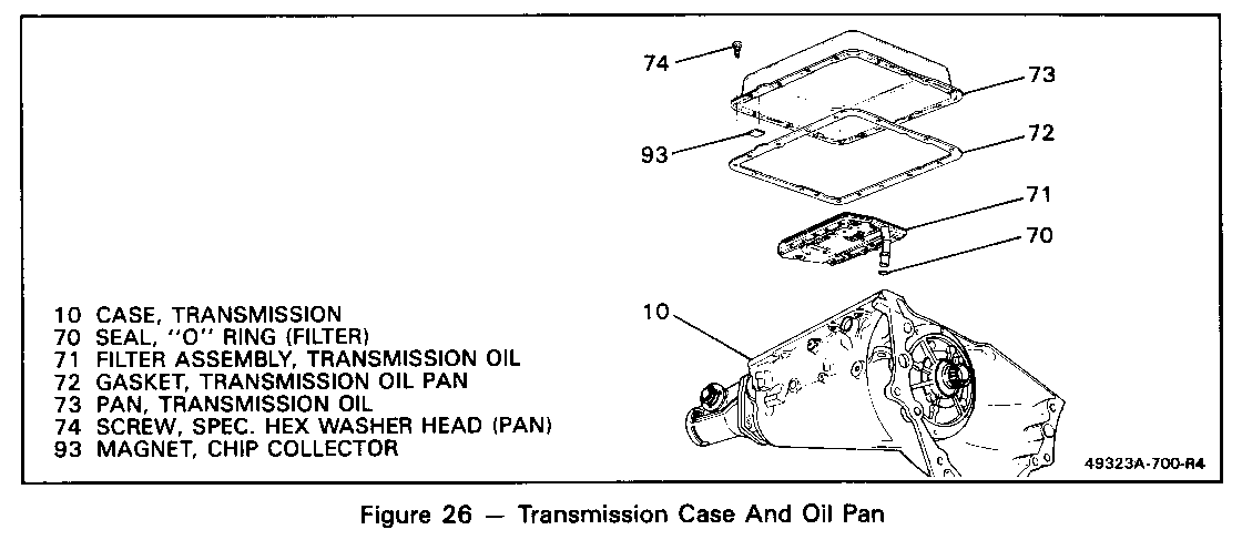
o Oil pan (73, Figure 26) is Imm deeper (to accommodate auxiliary valve body)
o New square, flexible chip collector magnet (93)
Date Of Change:
July 17, 1986, Julian Date 198, for all 1987 THM 700-R4 transmissions.All 1987 Service Replacement Transmission Assembly (STRA) models have the new oil pan and magnet. Service Action:
When servicing a 1987 model transmission, only use the new pan and magnet.
Service Parts:
Part Number Description Model Year Usage
8654700 Transmission Oil Pan 1982 through 1986
8663618 Transmission Oil Pan 1987 Only
NOTE : When current stock for 1982-1986 is used up, new pan and magnet will service 1982-1987 transmissions.
TRANSMISSION APPLICATIONS: SUBJECT:
1987 THM 700-R4 (MD8) New Temperature Switch And Solenoid Wiring Harness
TRANSMISSION MODELS:
FAM, MAM, MDM, MFM, MKM, MLM, Mmmi MPM, MRM, MVM, mwmt MXM, MZM, TJM, TKM, TVM, Txm
Vehicle Application:
M-van with: 4.3L engine . G-Van with: 4.3L, 5.0L, 5.7L engine R, V, C and K Truck with: 4.3L, 5.0L, 5.7L engine
Change To Assembly Components:
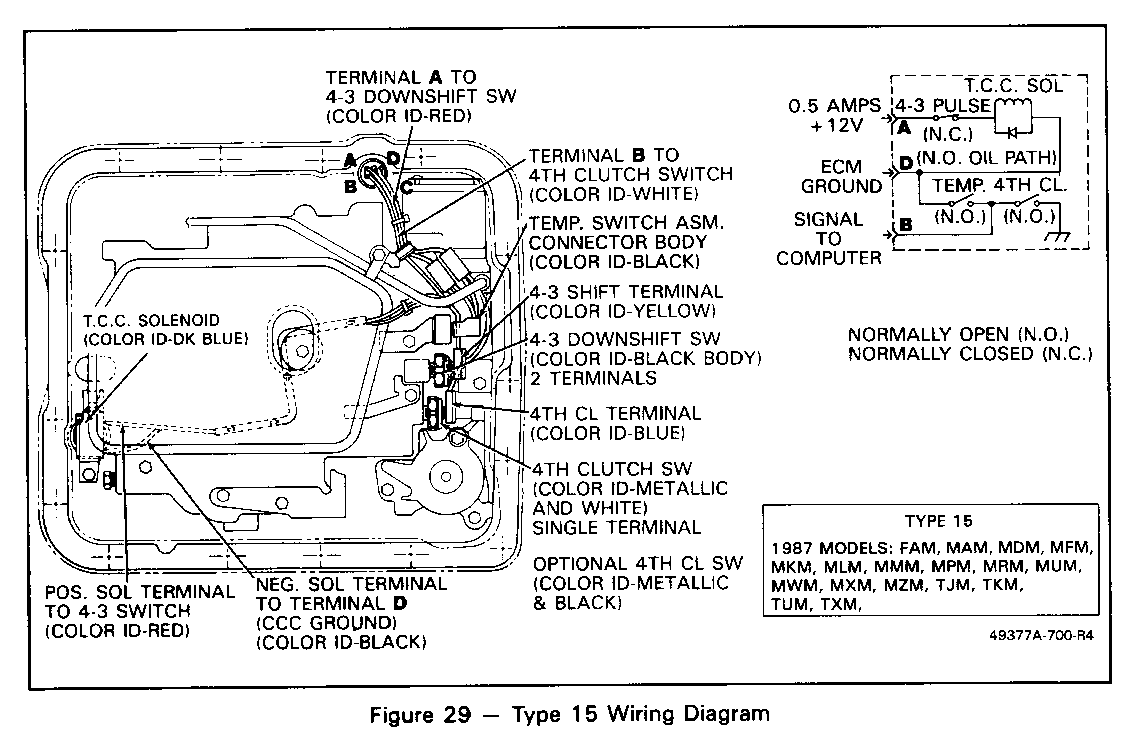
o New temperature switch and bracket assembly (Figure 29)
o New solenoid and wiring harness assembly (Type 15, Figu.re 29)
Date Of Change:
July 17, 1986, Julian Date 198, for 1987 THM 700-R4 transmission models as listed above. The equivalent 1987 Service Replacement Transmission Assembly (SRTA) models have the new temperature switch and solenoid wiring harness.
Service Action:
The new temperature switch is designed to prevent the transmission from overheating by applying the torque coverter clutch (TCC) under certain conditions. With the gear selector in D and the transmission operating in 4th gear, the temperature switch is normally open. If the transmission is operating in 4th gear without TCC apply and the fluid temperature reaches 126 - 135 degrees Celcius (259 - 275F) the switch closes. When closed, th torque converter clutch is applied to allow the fluid to cool to 106 - 119 C (222 - 246 F), when the switch opens and normal TCC operation resumes.
The new temperture switch is mounted to the control valve assembly by an existing bolt and can be serviced by removing the transmission oil pan. Service Parts Information:
Part Number Description
8654421 Temperature Switch (1987 models as listed)
8654415 Solenoid Assembly Complete (1987 models as listed)
General Motors bulletins are intended for use by professional technicians, not a "do-it-yourselfer". They are written to inform those technicians of conditions that may occur on some vehicles, or to provide information that could assist in the proper service of a vehicle. Properly trained technicians have the equipment, tools, safety instructions and know-how to do a job properly and safely. If a condition is described, do not assume that the bulletin applies to your vehicle, or that your vehicle will have that condition. See a General Motors dealer servicing your brand of General Motors vehicle for information on whether your vehicle may benefit from the information.
