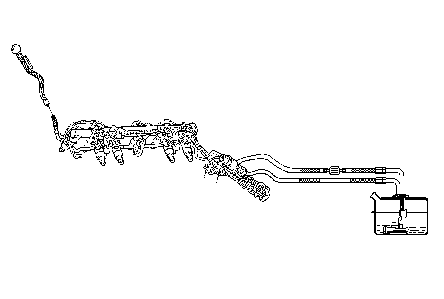
Fuel Injector Balance Test SFI

Circuit Description
The Fuel Injector Tester J 39021 , the Injector Switch Box J 39021-210 and the Injector Harness Connector J 39021-301 energize the injector for a precise amount of time allowing a measured amount of fuel into the manifold. This causes a drop in system fuel pressure that can be recorded and used to compare each injector. All injectors should be within the same pressure drop range, the average pressure drop value for all injectors is ±10 kPa (1.5 psi).
Test Description
The numbers below refer to the step numbers on the diagnostic table.
-
This step checks for the proper fuel pressure.
-
This step check for a decrease in the fuel pressure after the energizing each injector.
Step | Action | Value(s) | Yes | No |
|---|---|---|---|---|
1 | Was the Powertrain On-Board Diagnostic (OBD) System Check performed? | -- | ||
Is the fuel pressure within the specified value? | 380-430 kPa (56-62 psi) | Go to Fuel System Diagnosis | ||
Important: Before energizing each injector, run the fuel pump for 2 seconds. Does the fuel pressure drop approximately the specified value? | 10 kPa (1.5 psi) | System OK | ||
4 | Replace the appropriate fuel injector. Is the action complete? | -- | -- | |
5 |
Does the engine start and continue to run? | -- | ||
6 |
Select the DTC and the Failed This Ign. Are any DTCs displayed? | -- | Go to The Applicable DTC Table | |
7 | Using the scan tool, select the Capture Info and the Review Info. Are any DTCs displayed that have not been diagnosed? | -- | Go to The Applicable DTC Table | System OK |
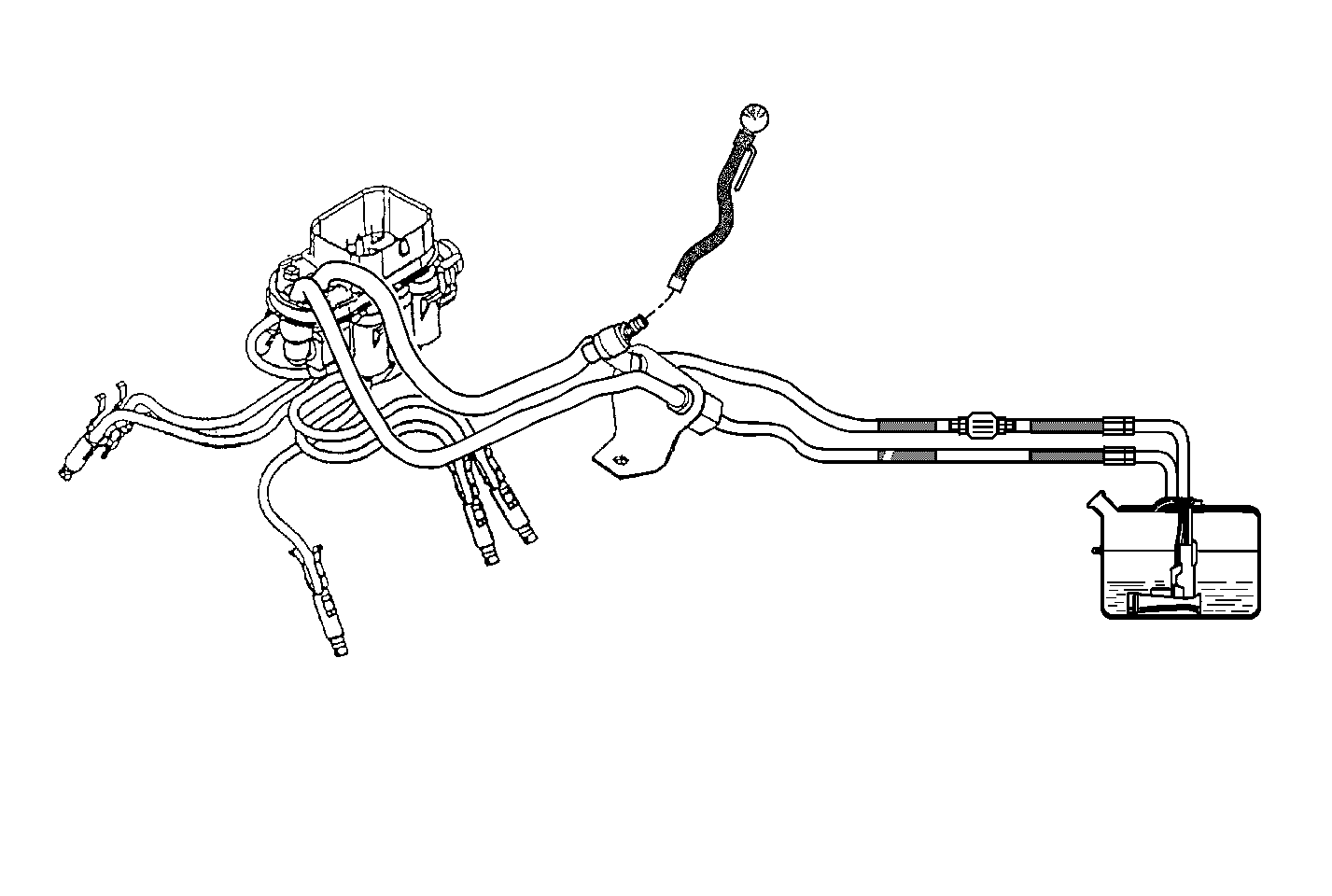
Fuel Injector Balance Test Central SFI

Circuit Description
The Fuel Injector Tester J 39021 , the Injector Switch Box J 39021-210 and the Injector Harness Connector J 39021-301 energize the injector for a precise amount of time allowing a measured amount of fuel into the manifold. This causes a drop in system fuel pressure that can be recorded and used to compare each injector. All injectors should be within the same pressure drop range, the average pressure drop value for all injectors is ±10 kPa (1.5 psi).
Test Description
The numbers below refer to the step numbers on the diagnostic table.
-
This step checks for the proper fuel pressure.
-
This step check for a decrease in the fuel pressure after the energizing each injector.
Step | Action | Value(s) | Yes | No |
|---|---|---|---|---|
1 | Was the Powertrain On-Board Diagnostic (OBD) System Check performed? | -- | ||
Is the fuel pressure within the specified value? | 415-455 kPa (60-66 psi) | Go to Fuel System Diagnosis | ||
Important: Before energizing each injector, run the fuel pump for 2 seconds. Does the fuel pressure drop approximately the specified value? | 10 kPa (1.5 psi) | System OK | ||
4 | Replace the appropriate injector and poppet nozzle assembly. Is the action complete? | -- | -- | |
5 |
Does the engine start and continue to run? | -- | ||
6 |
Select the DTC and the Failed This Ign. Are any DTCs displayed? | -- | Go to The Applicable DTC Table | |
7 | Using the scan tool, select the Capture Info and the Review Info. Are any DTCs displayed that have not been diagnosed? | -- | Go to The Applicable DTC Table | System OK |
