Go to
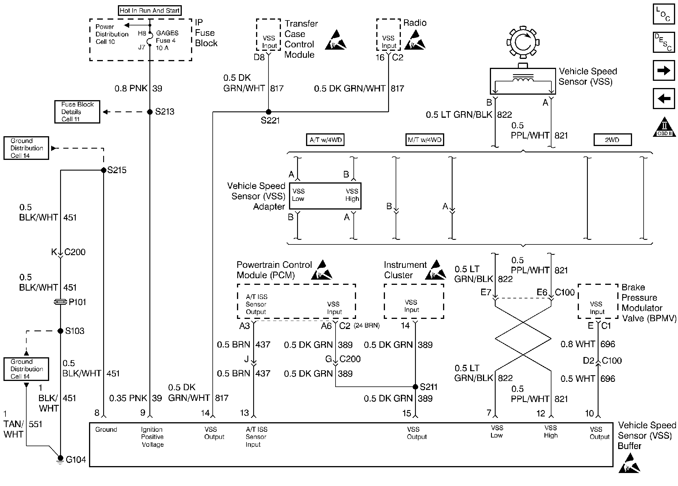
Transmission Vehicle Speed Sensor and Buffer

.
Circuit Description
The speed sensor circuit consists of a magnetic induction type sensor, a vehicle speed sensor buffer module and wiring. Gear teeth pressed on the output shaft induce an alternating current in the sensor. This signal is transmitted to the buffer. The buffer compensates for various axle ratios and converts the signal into a square wave for use by the speedometer, cruise control, antilock brake and PCM. The buffer sends two different signals to the PCM. This is a type D DTC.
Conditions for Setting the DTC
| • | Vehicle speed greater than 20 mph. |
| • | Four wheel low not selected. |
| • | VSS buffer calculated speed is less than half the transmission calculated speed. |
or
| • | VSS buffer calculated speed is greater than transmission calculated speed by 20 mph. |
| • | All conditions must be met for 2 seconds. |
Action Taken When the DTC Sets
No cruise control.
Conditions for Clearing the MIL/DTC
| • | A History DTC will clear when forty consecutive warm-up cycles that the diagnostic does not fail (coolant temperature has risen 5°C (40°F) from start up coolant temperature and engine coolant temperature exceeds 71°C (160°F) that same ignition cycle. |
| • | Use of a Scan tool |
Diagnostic Aids
Check connections at VSS buffer and PCM. Refer to 4L80E Diagnostic Trouble Codes in Automatic Transmission if DTC P0722 or DTC P0723 is also set.
Test Description
Number(s) below refer to number(s) on the Diagnostic Table.
-
This tests for B+ at VSS buffer.
-
This tests for proper ground path for vehicle speed sensor signal buffer.
Step | Action | Value(s) | Yes | No |
|---|---|---|---|---|
1 |
Important: Before clearing DTCs use the scan tool Capture Info to record freeze frame and failure records for reference, as data will be lost when Clear Info function is used. Was the On-Board Diagnostic (OBD) System Check performed? | -- | ||
2 |
With drive wheels rotating, does vehicle speed increase with drive wheel speed increase? | -- | ||
Is test light ON? | -- | |||
Back probe VSS buffer module ignition feed circuit to the ground circuit with a test light. Is the test light ON? | -- | |||
5 |
Does voltage increase on J 39200 with drive wheel increase? | -- | ||
6 | Does scan tool display a trans output speed (MPH) increase with drive wheel increase? | -- | ||
7 | DTC is intermittent. If no additional DTCs are stored, refer to Diagnostic Aids. If additional DTCs are stored refer to those chart(s) first. Are additional DTCs stored? | -- | Go to the Applicable DTC Table | Go to Diagnostic Aids |
8 | Repair the open in the ignition feed circuit. Is the action complete? | -- | -- | |
9 | Repair the open in the ground circuit. Is the action complete? | -- | -- | |
10 | Check the complete VSS input circuit for an open or short to ground. Was a repair performed? | -- | -- | |
11 | Check VSS output circuit for an open or short to ground. Was a repair performed? | -- | ||
12 | Check VSS output circuit for a poor connections at buffer module and PCM. Was a repair performed? | -- | ||
13 | Replace VSS Buffer module. Refer to Vehicle Speed Signal Buffer . Is the action complete? | -- | -- | |
14 | Replace the faulty PCM. Important: If the PCM is faulty, the new PCM must be programmed. Refer to Powertrain Control Module Replacement/Programming . Is the action complete? | -- | -- | |
15 |
Does the Scan Tool indicate that this diagnostic Ran and Passed? | -- | ||
16 | Using the Scan Tool, select Capture Info, Review Info. Are any DTCs displayed that have not been diagnosed? | -- | Go to the Applicable DTC Table | System OK |
