Removal Procedure
Tools Required
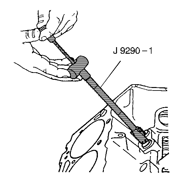
J 9290-01 Valve Lifter Remover (Slide Hammer Type)
- Remove the intake manifold. Refer to Intake Manifold Replacement .
- Remove the pushrods. Refer to Valve Rocker Arm and Push Rod Replacement .
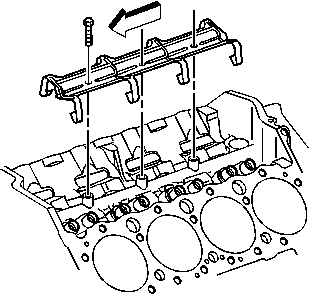
- Remove the valve lifter retainer and guides.
- Remove the valve lifters. Remove the valve lifters one at a time and place them in an organizer rack. The valve lifter must be installed in the same bore from which the valve lifters were removed. A stuck valve lifter can be removed using the J 9290-01 .
- Inspect the valve lifter body for scuffing and scoring. If the valve lifter body wall is worn or damaged, the mating bore in the block should also be checked.

| 5.1. | Check the fit of each valve lifter in its mating bore in the block. If the clearance is excessive, try a new valve lifter. |
| 5.2. | Check the roller for freedom of movement. The valve lifter must be smooth and even. If worn, pitted, or damaged, the mating camshaft lobe should also be checked. |
Installation Procedure
- Install the valve lifters into the block. Lubricate the valve lifters with High Viscosity Oil with Zinc GM P/N 12345501 or the equivalent.
- Install the valve lifter retainer and guides.
- Install the intake manifold. Refer to Intake Manifold Replacement .
- Install the pushrods. Refer to Valve Rocker Arm and Push Rod Replacement .
- Adjust the valves. Refer to Valve Lash Adjustment .
- Install the valve rocker arm cover and gasket. Refer to Valve Rocker Arm Cover Replacement .
Important:
• When new valve lifters or a new camshaft is installed, change
the engine oil and the oil filter. • High viscosity oil containing zinc GM P/N 12345501 or the equivalent
should be added to the engine oil. • Replace all valve lifters when a new camshaft is installed.

Tighten
Tighten the bolts to 16 N·m (12 lb ft).
Notice: Use the correct fastener in the correct location. Replacement fasteners must be the correct part number for that application. Fasteners requiring replacement or fasteners requiring the use of thread locking compound or sealant are identified in the service procedure. Do not use paints, lubricants, or corrosion inhibitors on fasteners or fastener joint surfaces unless specified. These coatings affect fastener torque and joint clamping force and may damage the fastener. Use the correct tightening sequence and specifications when installing fasteners in order to avoid damage to parts and systems.
