For 1990-2009 cars only
Tools Required
| • | J 7872 Magnetic Base Dial Indicator |
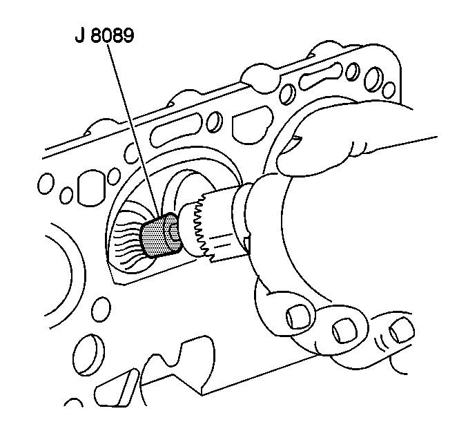
| • | J 8089 Wire Brush |
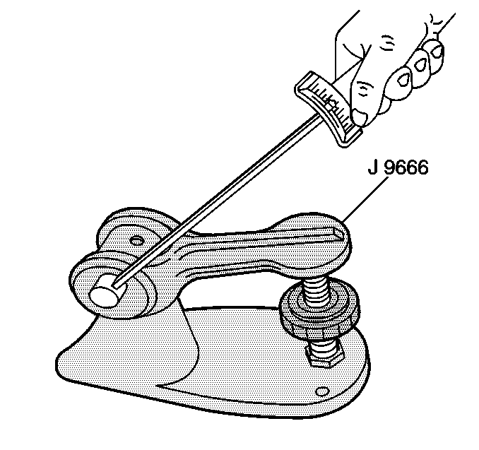
| • | J 9666 Valve Spring Tester |
- Clean the carbon from the combustion chambers, using the J 8089 .
- Clean the valve stems and heads on a wire wheel.
- Clean the carbon and old gasket from the cylinder head gasket surface.
- Clean the valve guides using a valve guide cleaner.
- Inspect the cylinder head for the following conditions:
- Inspect the valves for the following conditions:
- Grind or replace the valves as needed.
- Check the valve stems for scoring or excessive wear. Stems must not be bent.
- Inspect the valve seats for pitting or other damage. Grind or reface as needed.
- Inspect the exhaust valve rotators. The rotators should rotate smoothly without binding.
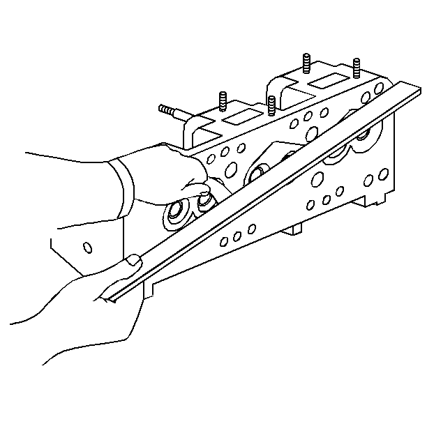
- Inspect the cylinder head for warpage. When the warpage is greater than 0.15 mm (0.006 in) longitudinally, or 0.08 mm (0.003 in) transversely, replace the cylinder head.
- Inspect the prechambers for cracks.
- Cylinder head thickness (valve rocker arm cover gasket rail to head gasket surface) must be at least 97.87 mm (3.853 in).
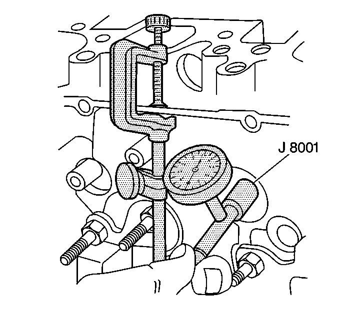
- Measure the valve stem to guide bore clearance using the following procedure:
- Measure the valve spring tension using the following procedure:
- The cylinder head bolts were installed with a thread locker. Use a power wire brush to clean the entire head bolt.
- Replace the head bolt if any of the following conditions exist:

| • | Cracks in the exhaust ports |
| • | Cracks in the combustion chambers |
| • | External cracks to the coolant chamber |
| • | Gasket surfaces should be free of damage |
| • | Burning |
| • | Pitting |
| • | Warpage |

| • | Replace any prechambers with facial cracks longer than 5 mm (0.20 in). |
| • | Service prechambers are available in standard and 0.25 mm (0.010 in) oversize. |
Notice: Resurfacing the cylinder head is not recommended due to the extremely close valve to piston clearances.
Notice: Excessive oil consumption and component damage may result from excessive valve stem to guide bore clearance. Insufficient clearance may cause noisy and sticky functioning of the valve and disturb the smoothness of the engine.

| 14.1. | Attach the J 7872 on one side of the cylinder head valve rocker arm cover gasket rail. |
| 14.2. | Zero in the dial indicator. |
| 14.3. | Observe the dial indicator movement while moving the valve from side to side (crosswise to the head). The dial indicator measurement must be taken just above the valve guide bore. |
| 14.4. | Drop the valve head about 1.6 mm (0.063 in) off the valve seat. |
| 14.5. | Move the stem of the valve from side to side using light pressure to obtain a clearance reading. If the clearance exceeds specifications, it will be necessary to ream the valve guide bores for oversize valves. |

| 15.1. | Using the J 9666 , compress the valve springs to the specified tension. |
| 15.2. | Check the valve spring height. Valve springs should be replaced if not within specification. Refer to Engine Mechanical Specifications . |
| • | Pitting or pulling of the threads |
| • | Pitting of the shaft |
| • | Excessive corrosion or stripping of the head |
