Water Pump Replacement Gasoline Engines
Removal Procedure
- Drain the coolant from the radiator. Refer to
Cooling System Draining and Filling
.
- Remove the upper fan shroud. Refer to
Fan Shroud Replacement
.
- Remove the drive belt. Refer to the appropriate procedure:
- Remove the fan, the fan clutch, and the pulley from the coolant
pump. Refer to
Fan Clutch Replacement
.
- Disconnect the radiator outlet hose from the coolant pump. Refer
to
Radiator Hose Replacement
.
- Disconnect the heater hose from the coolant pump. Refer to
Heater Hoses Replacement
in HVAC Systems with
A/C - Manual.
- On the 7.4L engine, disconnect the bypass hose.
- For the 4.3L, remove the
bolts.
- Remove the coolant pump from the engine block.
- Clean the mating surfaces on the coolant pump and the engine block.
- For the 5.0L and 5.7L,
remove the bolts.
- Remove the coolant pump from the engine block.
- Clean the mating surfaces on the coolant pump and the engine block.
- For the 7.4L, remove the
bolts.
- Remove the coolant pump from the engine block.
- Clean the mating surfaces on the coolant pump and the engine block.
Installation Procedure
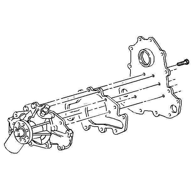
- On the 4.3L, install the
coolant pump to the engine block.
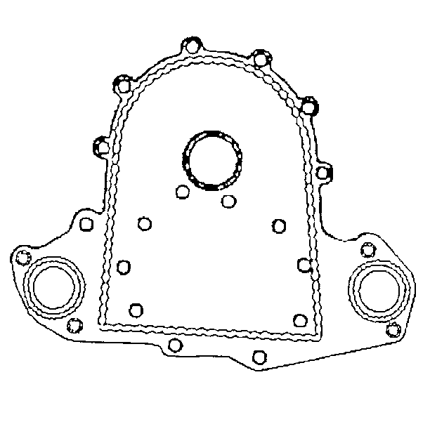
- Install the new gaskets.
Notice: Use the correct fastener in the correct location. Replacement fasteners
must be the correct part number for that application. Fasteners requiring
replacement or fasteners requiring the use of thread locking compound or sealant
are identified in the service procedure. Do not use paints, lubricants, or
corrosion inhibitors on fasteners or fastener joint surfaces unless specified.
These coatings affect fastener torque and joint clamping force and may damage
the fastener. Use the correct tightening sequence and specifications when
installing fasteners in order to avoid damage to parts and systems.
- Install the bolts.
Tighten
Tighten the bolts to 41 N·m (30 lb ft).
- On the 5.0L and 5.7L,
install the coolant pump to the engine block.
- Install the new gaskets.
- Install the bolts.
Tighten
Tighten the bolts to 41 N·m (30 lb ft).
- On the 7.4L, install the
coolant pump to the engine block.
- Install the new gaskets.
- Install the bolts.
Tighten
Tighten the bolts to 41 N·m (30 lb ft).
- Connect the radiator outlet hose to the coolant pump. Refer to
Radiator Hose Replacement
.
- Connect the heater hose to the coolant pump. Refer to
Heater Hoses Replacement
in HVAC Systems with
A/C - Manual.
- On the 7.4L engine, connect the bypass hose.
- Install the coolant pump pulley, the fan, and fan clutch to the
coolant pump hub. Refer to
Fan Clutch Replacement
.
- Install the drive belt. Refer to the appropriate procedure:
- Install the upper fan shroud. Refer to
Fan Shroud Replacement
.
- Start the engine. Run the engine, with the radiator cap removed,
until the upper radiator hose becomes hot (This indicates that the thermostat
is open).
- While the engine is running at idle speed, add coolant to the
radiator, until the level reaches the bottom of the filler neck. Refer to
Cooling System Draining and Filling
.
- Install the radiator cap.
Make sure that the cap arrows line up with the overflow tube.
- Inspect the cooling system for leaks.
Water Pump Replacement Diesel Engines
Removal Procedure
Caution: Unless directed otherwise, the ignition and start switch must be in the OFF or LOCK position, and all electrical loads must be OFF before servicing
any electrical component. Disconnect the negative battery cable to prevent an electrical spark should a tool or equipment come in contact with an exposed electrical terminal. Failure to follow these precautions may result in personal injury and/or damage to
the vehicle or its components.
- Disconnect
the negative battery cable.
- Drain the coolant from the radiator. Refer to
Cooling System Draining and Filling
.
- Remove the fan shroud. Refer to
Fan Shroud Replacement
.
- Remove the drive belt. Refer to the appropriate procedure:
- Remove the fan and fan clutch. Refer to
Fan Clutch Replacement
.
- Raise the vehicle. Support the vehicle with safety stands. Refer
to
Lifting and Jacking the Vehicle
in General Information.
- Remove the following vacuum pump components. Refer to Vacuum Pump Replacement
in Vacuum Pump.
| 7.1. | The mounting bracket nuts |
| 7.2. | The bolt securing the vacuum pump bracket and the generator |
| 7.3. | The vacuum pump and the bracket |
- Remove the power steering pump. Lay the pump aside. Refer to
Power Steering Pump Replacement
in Power Steering
System.
- Disconnect the lower radiator hose from the coolant pump. Refer
to
Radiator Hose Replacement
.
- Disconnect the bypass hose from the coolant pump.
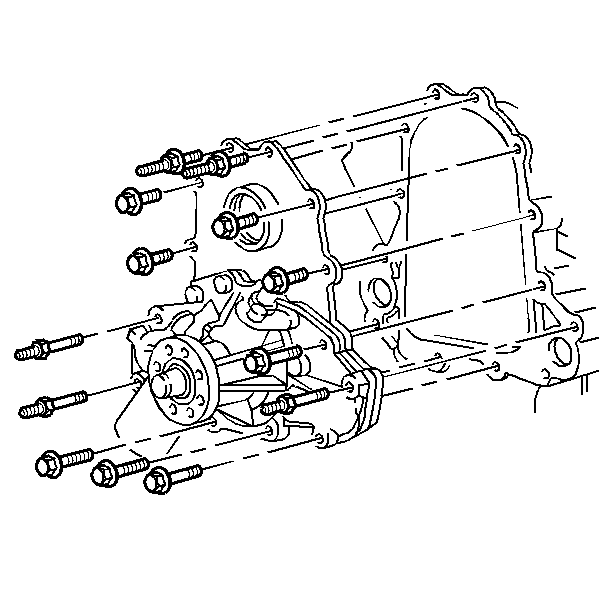
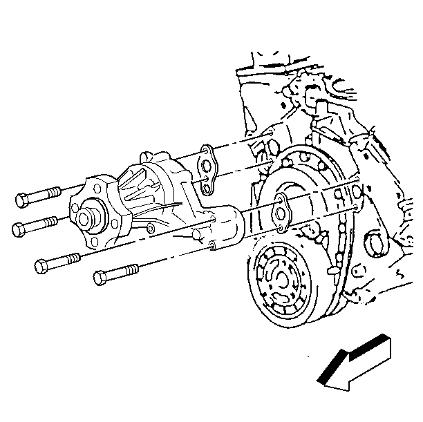
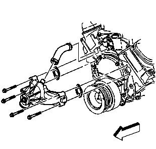
- Remove the bolts, the
studs, the coolant pump backing plate and the coolant pump.
- Remove the bolt from the
rear of the coolant pump backing plate.
- Remove the coolant pump and the gasket from the backing plate.
Important: All of the flanges must be free of oil.
- Clean the following mating surfaces:
| • | The coolant pump backing plate (both sides) |
Installation Procedure
- Install the gasket.
- Install the coolant pump to the coolant pump backing plate.
Notice: Use the correct fastener in the correct location. Replacement fasteners
must be the correct part number for that application. Fasteners requiring
replacement or fasteners requiring the use of thread locking compound or sealant
are identified in the service procedure. Do not use paints, lubricants, or
corrosion inhibitors on fasteners or fastener joint surfaces unless specified.
These coatings affect fastener torque and joint clamping force and may damage
the fastener. Use the correct tightening sequence and specifications when
installing fasteners in order to avoid damage to parts and systems.
- Install the bolt.
Tighten
Tighten the bolt to 23 N·m (17 lb ft).
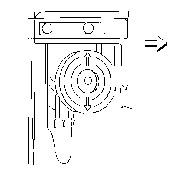
- Apply anaerobic sealer
GM P/N 1052357, or equivalent to the coolant pump backing plate. The sealer
must be wet to the touch when tightening the bolts.
- Install the coolant pump
and the coolant pump backing plate to the engine.
- Install the bolts and the studs.
Tighten
Tighten the bolts and the studs to 42 N·m (31 lb ft).
- Connect the bypass hose.
- Connect the lower radiator hose. Refer to
Radiator Hose Replacement
.
- Install the power steering bracket and the pump. Refer to
Power Steering Pump Replacement
in Power Steering
System.
- Install the vacuum pump and the bracket. Refer to Vacuum Pump Replacement
in Vacuum Pump.
- Install the bolt that holds the vacuum pump and the generator.
Refer to Vacuum Pump Replacement
in Vacuum Pump.
- Install the fan and fan clutch assembly and the coolant pump pulley.
Refer to
Fan Clutch Replacement
.
- Install the drive belt. Refer to the appropriate procedure:
- Install the fan shroud. Refer to
Fan Shroud Replacement
.
- Connect the negative battery cable.
- Fill the surge tank with coolant. Refer to
Cooling System Draining and Filling
.
- Start the engine. Run the engine with the surge tank cap removed,
until the upper radiator hose becomes hot. (This indicates that the thermostat
is open).
- While the engine is running at idle speed, add coolant to the
surge tank until the level reaches the FULL mark. Refer to
Cooling System Draining and Filling
.
- Install the surge tank
cap. Make sure the cap arrows line up with the overflow tube.
- Inspect the cooling system for leaks.
