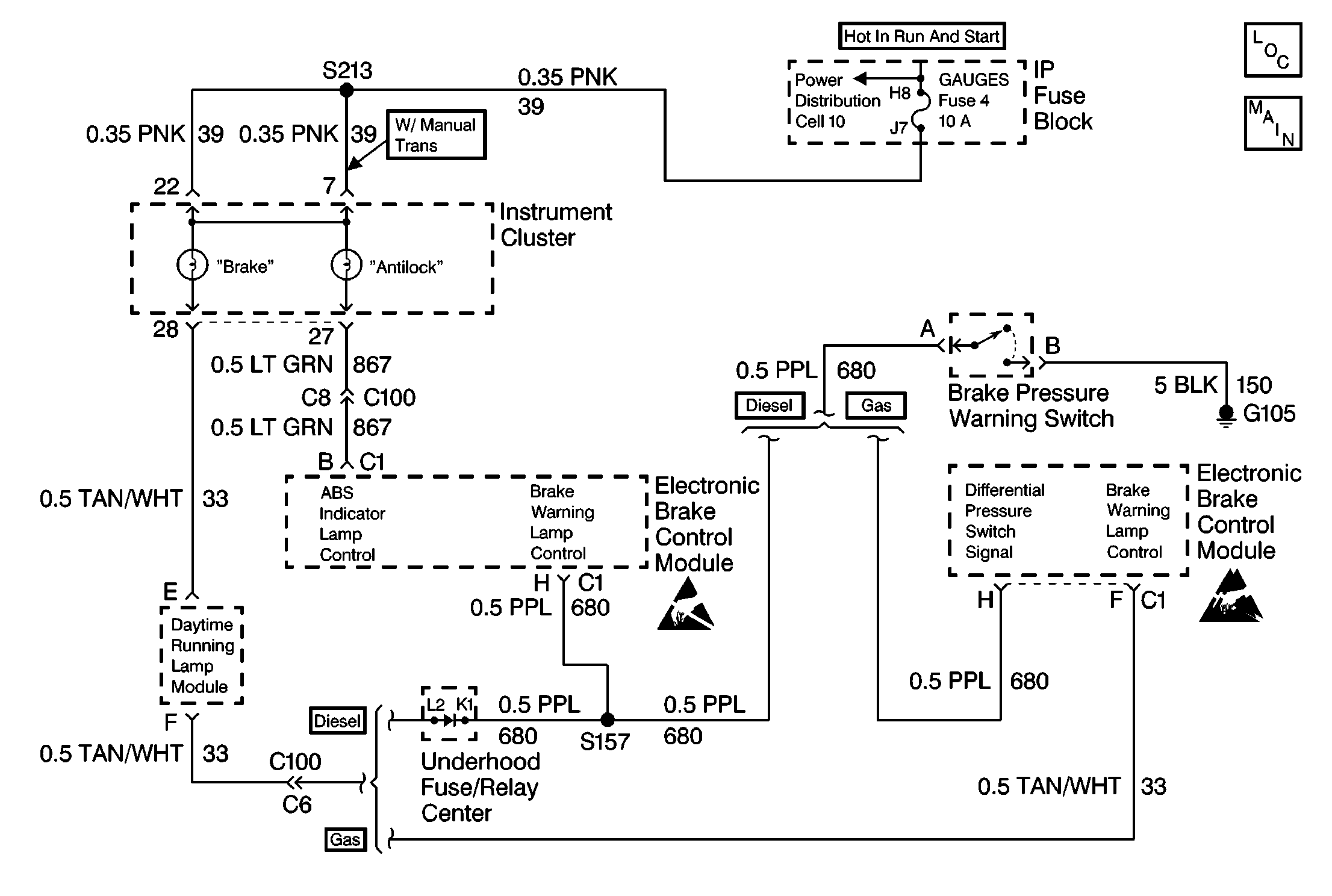
Circuit Description
The red BRAKE warning lamp is supplied ignition voltage through the GAUGES fuse. The BRAKE warning lamp can be illuminated by the EBCM, Daytime Running Lights Module (DRL) or Brake Pressure Warning Switch. If a DTC C0288 sets, the EBCM will store in memory but will not disable the ABS. If a DTC C0288 is in memory, the EBCM will not attempt to perform a BRAKE warning lamp bulb check at startup. Also the EBCM will not attempt to use the BRAKE indicator lamp as a backup if the ABS indicator lamp operation is inhibited by a DTC C0286.
Conditions for Setting the DTC
| • | High voltage is present on the BRAKE warning lamp circuit when the circuit is expected to be low (lamp commanded on by the EBCM) |
| • | Anything that keeps the Brake warning lamp circuit high when the lamp is supposed to be illuminated (such as a short to voltage on CKT 33) |
Action Taken When the DTC Sets
No action taken, the ABS is not disabled.
Conditions for Clearing the MIL/DTC
| • | Repair the conditions responsible for setting the DTC |
| • | Use the Scan Tool Clear DTCs function |
Diagnostic Aids
DTC C0288 is usually set by a short to voltage in the wiring between the brake warning lamp and the EBCM.
Test Description
The numbers below refer to the steps in the diagnostic table.
-
Determines if the BRAKE warning lamp circuit is operating properly when controlled by the EBCM (with diesel engines).
-
This step determines which variation of circuitry the vehicle is equipped.
-
This step determines if the BRAKE warning lamp circuit is operating properly without the EBCM (with diesel engines).
-
This step decides between a constant or intermittent short to voltage condition.
-
This step determines if the BRAKE warning lamp circuit is operating properly without the EBCM (with gas engines).
-
This step decides between a constant or intermittent short to voltage condition.
Step | Action | Value(s) | Yes | No | ||||||
|---|---|---|---|---|---|---|---|---|---|---|
1 | Was the ABS Diagnostic System Check performed? | -- | Go to Diagnostic System Check | |||||||
Did the BRAKE warning lamp turn on and then off after three seconds? | -- | |||||||||
Take note of the engine type in the vehicle. Is the engine a Diesel type Engine? | -- | |||||||||
Does the BRAKE warning lamp turn on? | -- | |||||||||
Inspect the jumper wire fuse Is the fuse open? | -- | |||||||||
6 | Malfunction is intermittent. Perform the following:
Is repair complete? | -- | Go to Diagnostic System Check | -- | ||||||
7 | Replace the EBCM. Refer to Electronic Brake Control Module Replacement . Is repair complete? | -- | Go to Diagnostic System Check | -- | ||||||
8 | Repair a short to voltage in CKT 680. Is repair complete? | -- | Go to Diagnostic System Check | -- | ||||||
Does the BRAKE warning lamp turn on? | -- | |||||||||
Inspect the jumper wire fuse. Is the fuse open? | -- | |||||||||
11 | Repair a short to voltage in CKT 33. Is repair complete? | -- | Go to Diagnostic System Check | -- |
