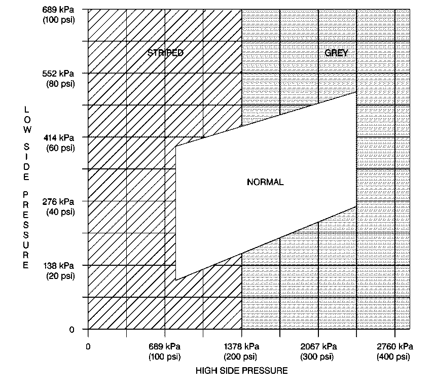
| Table 1: | Gray Area Diagnosis and Service |
| Table 2: | Striped Area Diagnosis and Service |
The compressor is a scroll compressor that matches the air conditioning demand by changing the compressor stroke, instead of cycling the compressor clutch. A capacity control valve located in the compressor senses the low side pressure and causes the compressor to adjust to A/C cooling demands. The compressor always runs and the system does not cycle. However, the compressor may cycle if the cooling load is not reduced enough by the capacity control valve.
Preliminary Checks
| • | Check the proper operation of the cooling fans. |
| • | Check for system voltage above 10.5 Volts. |
| • | Check the A/C fuse and replace as necessary. |
| • | Check the A/C blower operation and repair as necessary. |
| • | Check the clutch coil electrical connection and repair as necessary. |
| • | Check the drive belt and replace if damaged or missing. |
| • | Check the condenser for restricted air flow and clean as necessary. |
Refer to the following tables when you are diagnosing insufficient cooling complaints.
Step | Action | Value(s) | Yes | No | ||||||
|---|---|---|---|---|---|---|---|---|---|---|
1 | Inspect for any stored DTCs. Are any DTCs stored? | -- | Go to Step 3 | Go to Step 2 | ||||||
2 | Connect the J 39500-B . Are the pressures above 350 kPa (50 psi)? | -- | Go to Step 4 | Go to Step 8 | ||||||
3 | Correct any stored DTCs. Refer to Diagnostic Trouble Code (DTC) List . Does the complaint persist? | -- | Go to Step 1 | System OK | ||||||
4 | Inspect and correct for a blown Air Conditioner (A/C) fuse. Does the complaint persist? | -- | Go to Step 5 | System OK | ||||||
5 |
Does the A/C clutch rotate smoothly? | -- | Go to Step 6 | System OK | ||||||
6 | Inspect and correct for the following conditions:
Does the complaint persist? | -- | Go to Step 7 | |||||||
7 | Read the DCS for Bulletins and Hints. Follow the procedures indicated. Does the complaint persist? | -- | Go to Step 10 | System OK | ||||||
8 |
Did you find a leak? | -- | Go to Step 9 | Go to Step 10 | ||||||
9 |
Does the complaint persist? | -- | Go to Step 2 | System OK | ||||||
10 | Perform an A/C Performance Check using the following steps:
Does the A/C performance meet the requirement on the Performance Chart? | -- | Go to Step 11 | Go to HVAC High Side vs. Low Side Pressure Table | ||||||
11 | Was the customer complaint made due to high temperature and/or high humidity? | -- | System OK | Go to Step 12 | ||||||
12 | Perform a leak test. Refer to Leak Testing . Did you find a leak? | -- | Go to Step 13 | System OK | ||||||
13 | Evacuate and recharge the A/C system. Refer to Refrigerant Recovery and Recharging . Does the complaint persist? | -- | Go to Step 10 | System OK |
High Side vs. Low Side Pressure Table

Problem | Action | ||||||||
|---|---|---|---|---|---|---|---|---|---|
|
Important: The clutch may cycle if the discharge pressure exceeds 2758 kPa (400 psi). or if system voltage drops below 10.5 Volts. | |||||||||
Improper condenser operation | Improper condenser operation may result from one of the following causes:
| ||||||||
High side refrigerant restriction |
| ||||||||
Refrigerant system overcharged (high discharge and high suction pressures) | The clutch may cycle ON/OFF and cause compressor noise. Evacuate and recharge the system with the proper amount of refrigerant. Refer to Refrigerant Recovery and Recharging . | ||||||||
Expansion tube (orifice) blocked |
| ||||||||
Air in system (High discharge and high suction pressures). |
| ||||||||
Problem | Action | ||||||
|---|---|---|---|---|---|---|---|
The compressor is damaged internally. |
| ||||||
The expansion tube (orifice) is missing. | Feel the liquid line after the expansion tube. If the line is warm, discharge the system and inspect for proper installation of the expansion tube. If the expansion tube or O-ring is missing, replace the expansion tube. Refer to Auxiliary Expansion (Orifice) Tube Replacement . | ||||||
The refrigerant system is undercharged. |
| ||||||
The expansion tube (orifice) is blocked. |
|
