For 1990-2009 cars only
Removal Procedure
- Disconnect the negative battery cable.
- For vehicles equipped with tilt wheel, move the steering column to the lowest position, if the vehicle is not equipped with a tilt steering column, you may have to lower the column.
- Remove the four clips across the top edge, and the four clips across the bottom edge that retain the bezel to the IP by gently pulling toward the inside of the vehicle.
- Disconnect the electrical connectors from the headlamp switch and the accessory switches.
Caution: Unless directed otherwise, the ignition and start switch must be in the OFF or LOCK position, and all electrical loads must be OFF before servicing any electrical component. Disconnect the negative battery cable to prevent an electrical spark should a tool or equipment come in contact with an exposed electrical terminal. Failure to follow these precautions may result in personal injury and/or damage to the vehicle or its components.
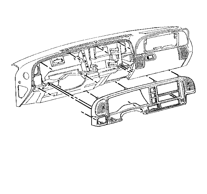
Installation Procedure
- Connect the electrical connectors for the headlamp switch and the accessory switches.
- Press the bezel into the IP making sure that the clips line up with the holes in the IP.
- Connect the negative battery cable.
