Steering Gear Pitman Shaft Over-Center Preload Adjustment - Off Vehicle Saginaw - 708 Model
Steering Gear Adjustments
Important: Any steering gear adjustment is made only as a correction and not as a periodic adjustment.
Remove the gear from the vehicle prior to any adjustments.
- Drain the power steering fluid from the gear.
- Mount the gear in a vise.
- Adjust the following:
Important:
• Adjust the worm thrust bearing preload first, then adjust the
pitman shaft over-center preload. • The worm thrust bearing preload is controlled by the amount of
compression force exerted by the adjuster nut assembly on the flat races. • The pitman shaft over-center preload is controlled by the pitman
shaft adjuster screw, which determines the clearance between the rack piston
and the pitman shaft sector teeth.
| 3.1. | The worm thrust bearing preload |
| 3.2. | The pitman shaft over-center preload adjustment |
Worm Thrust Bearing Preload Adjustment
Tools Required
J 42882 Adjuster Nut Socket
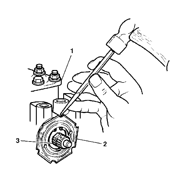
- Rotate the stub shaft (3) back and forth in order to drain the power steering fluid.
- Remove the coupling shield retainer and the lock nut (2) from the steering gear housing (1) using a drift and a hammer.
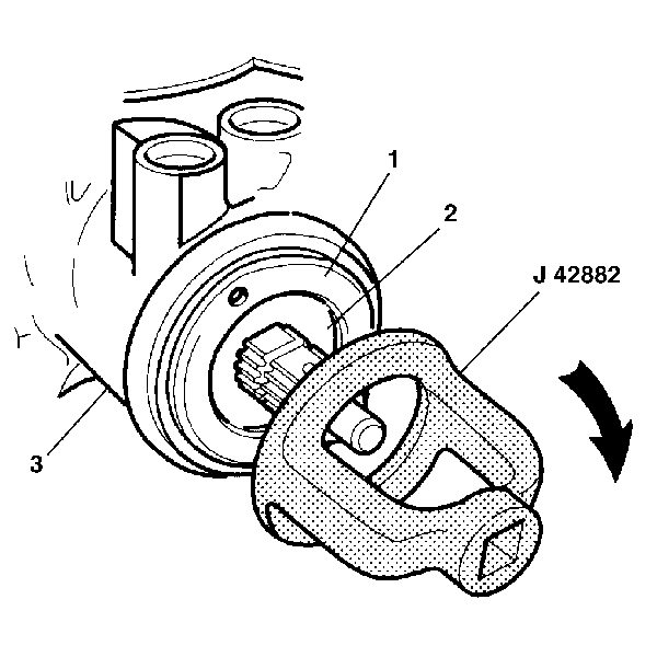
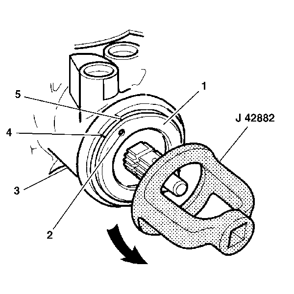
- Turn the adjuster nut assembly (1) clockwise using J 42882 until the adjuster nut assembly (1) and the thrust support assembly (2) are firmly bottomed in the steering gear housing (3).
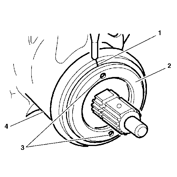
- Place an index mark (1) on the steering gear housing (4) parallel with one of the holes (3) in the adjuster nut assembly (2).
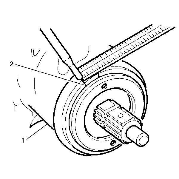
- Measure back counterclockwise 13 mm (½ inch).
- Place a second mark (2) on the steering gear housing (1).
- Using J 42882 and a torque wrench, turn the adjuster nut assembly (1) counterclockwise 15-25 degrees in order to align the hole (2) in the adjuster nut assembly (1) with the second mark (4) on the steering gear housing (3).
- Install the coupling shield retainer and the lock nut (2).
- Hold the adjuster nut assembly in position in order to maintain alignment of the marks.
- Tighten the coupling shield retainer and the lock nut (2) using a drift in a notch.
Notice: Use the correct fastener in the correct location. Replacement fasteners must be the correct part number for that application. Fasteners requiring replacement or fasteners requiring the use of thread locking compound or sealant are identified in the service procedure. Do not use paints, lubricants, or corrosion inhibitors on fasteners or fastener joint surfaces unless specified. These coatings affect fastener torque and joint clamping force and may damage the fastener. Use the correct tightening sequence and specifications when installing fasteners in order to avoid damage to parts and systems.
Tighten
Tighten the adjuster nut assembly (1) to 28-31 N·m
(20-23 lb ft).

Pitman Shaft Over-Center Preload Adjustment
- Rotate the stub shaft (3) back and forth in order to drain the power steering fluid.
- Loosen the adjuster lock nut (4).
- Turn the pitman shaft adjuster screw (1) counterclockwise until the screw is fully extended.
- Turn the pitman shaft adjuster screw (1) clockwise 1 full turn.
- Rotate the stub shaft (3) from stop to stop, using a 12-point socket while counting the number of turns.
- Starting at either stop, turn the stub shaft (3) back half of the total number of turns. This is the center of the gear.
- Ensure that the gear is centered by verifying the following items:
- Align the master spline (5) on the pitman shaft (4) with the adjuster screw (1).
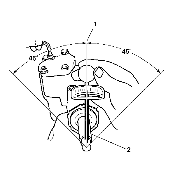
- Place a torque wrench on the stub shaft (2) with the handle in the vertical position.
- Rotate the stub shaft (2) 45 degrees from each side of the center of the stub shaft. The stub shaft (2) must rotate smoothly.
- Record the worm bearing preload measured on or near the center (1). The recorded bearing preload must be 0.7-1.7 N·m (6-15 lb in) with the worm and the ballnut installed. If the torque is outside of this range, readjust or repair the steering gear assembly as required.
- In order to obtain the correct preload torque, adjust the over-center torque by turning the pitman shaft adjuster screw clockwise.
- Add 0.7-1.1 N·m (6-10 lb in) torque to the previously measured worm bearing preload torque.
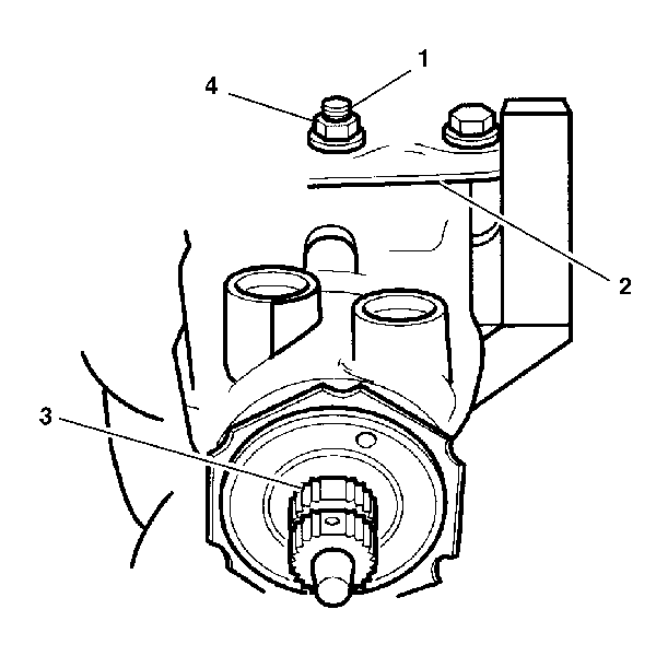
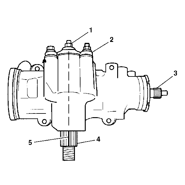
| • | The flat on the stub shaft (3) faces upward. |
| • | The flat on the stub shaft (3) is parallel with the side cover (2). |
Tighten
Tighten the adjuster lock nut to 49 N·m (36 lb ft).
Prevent the adjuster screw from turning while tightening the adjuster lock
nut.
