AUXILARY FUEL TANK CONTROL DIAGNOSE AND VERIFY OPERATION

MODELS: 1981-1983 C/K 1500 THROUGH 3500 LIGHT DUTY WITH AUXILIARY FUEL TANK RPO NL2
The following material is being provided to update 1981 through 1983 Auxiliary Fuel Tank Control Service Manual information. It provides a means to diagnosis and verify operation of the Dual Fuel Tank (Option NL2) Selector Valve on C/K Series Trucks.
AUXILIARY FUEL TANK SWITCH
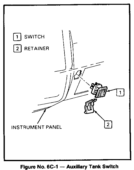
The auxiliary fuel tank switch (Figure No. 6C-1) is located on the instrument panel, just left of the ashtray. The switch controls fuel tank switching and fuel gage indication in a single operation.
To operate:
Depress the rocker switch at the TOP for the Right Hand (R.H.) tank; at the BOTTOM for the Left Hand (L.H.) tank. When pressing the switch, a detent will be felt. Continue pressing beyond the detent and hold momentarily (1 second or more) to fully activate the tank switching unit. Release the switch and it will return to the detent position.
FUEL TANK SELECTOR VALVE CHECK
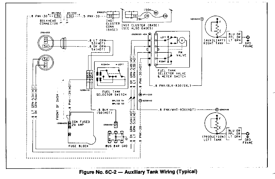
Before attempting any electrical diagnosis, insure that all electrical and ground connections are clean and tight. (Figure No. 6C-2).
A simple check can be made to determine if the Fuel Tank Selector Valve is operating by listening for audible operation of the motor inside the selector valve, when the switch is pressed.
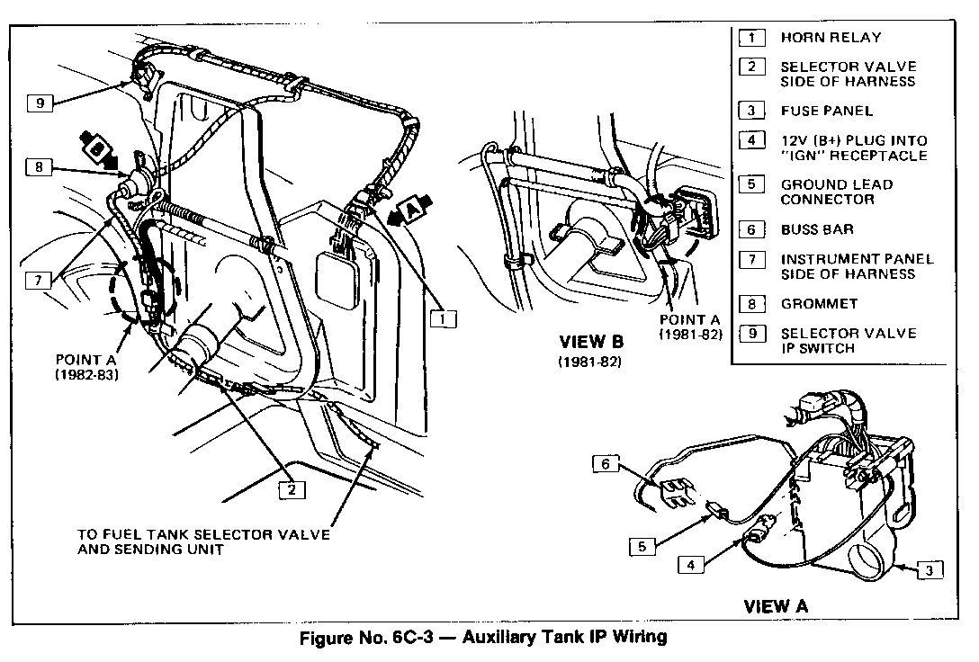
CHECKING INSTRUMENT PANEL SIDE OF HARNESS (Figure No. 6C-3)
1. Disconnect selector valve harness at point A (Figure No. 6C-3).
2. With ignition on, connect one lead of a test light to one terminal of the female harness connector. Probe remaining terminal. Test light should light in both switch positions. If OK, go to Step 7. If light does not light, continue with Step 3.
3. Check for proper ground connection (Black or Black with Pink wire) at Buss Bar (Figure No. 6C-3).
4. Check for proper connection to ignition receptical in Fuse Panel (Figure No. 6C-3).
5. If ground and ignition connections are OK, check for proper connection at selector valve switch. Check for bent terminals on back of switch and in switch connector and for B at pink wire and Ground at black wire in switch connector.
6. Repeat Step 2. If OK, continue with Step 7.
7. With ignition on, connect one lead of a test light to ground and probe light Green wire of female connector at Point A (Figure No. 6C-3). Test light should light to one switch position only. If OK, proceed with selector valve hamess check. If light does not light in either position, continue with Step 8.
8. Replace selector valve switch (Figure No. 6C-1).
9. Repeat Step 2. If not OK, there is an open in harness between switch and connection Point A. Repair or replace as necessary.
If the conditions in Steps 2 and 7 are corrected, but a problem still exists, perform check of selector valve side of harness.
CHECKING SELECTOR VALVE SIDE OF HARNESS (Includes Fuel Tank Selector Valve)
Before performing this portion of the procedure, be sure there is sufficient fuel (approximately 10 gallons in one tank and 5 gallons in the other) in both tanks.
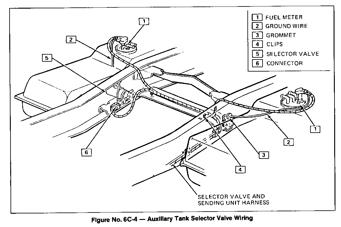
1. Remove harness connector from fuel tank selector valve (Figure No. 6C4).
2. Connect a known good selector valve and with ignition switch, ON activate instrument panel switch and note gage reading of both right and left hand tank.
If a change is indicated between tanks, system is operating properly. If not, repair open in harness between selector valve and Point A (Figure No. 6C-3). If a change is indicated between tanks when switch is activated, original selector valve was defective, replace with new valve.
If fuel gage operates, but not accurately, refer to Section 8C for fuel gage diagnosis.
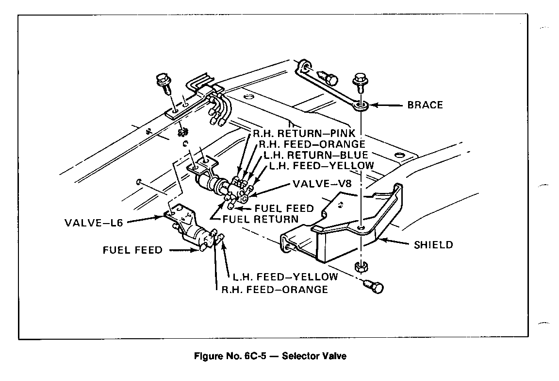
FUEL TANK SELECTOR VALVE Replacement (Figure No. 6C-5)
1. Disconnect battery.
2. Remove hose shield and brace.
3. Disconnect electrical connector from selector valve.
4. Remove fuel and vapor hoses noting their position for later installation.
5. Remove two screws holding valve to frame and remove valve.
6. Install valve and tighten screws.
7. Install fuel and vapor hoses in same positions noted at removal.
8. Connect electrical connector to selector valve.
9. Install brace and hose shield.
10. Connect battery.
General Motors bulletins are intended for use by professional technicians, not a "do-it-yourselfer". They are written to inform those technicians of conditions that may occur on some vehicles, or to provide information that could assist in the proper service of a vehicle. Properly trained technicians have the equipment, tools, safety instructions and know-how to do a job properly and safely. If a condition is described, do not assume that the bulletin applies to your vehicle, or that your vehicle will have that condition. See a General Motors dealer servicing your brand of General Motors vehicle for information on whether your vehicle may benefit from the information.
