HARD BRAKE PEDAL FEEL-COLD ENG QUICK BRAKE REAPPLY

MODELS: 1987 - 1988 R/V-20 WITH 5.7L (L05) OR 7.4L (L19) WITH JB7 BRAKES 1984 - 1986 C/K-20 WITH 5.7L (LT9) OR 7.4L (LE8) WITH JB7 BRAKES
A condition described as a hard brake pedal feel with a cold engine or upon quick reapply of the brakes may be caused by reduced vacuum at the brake booster Vehicles with this condition can be improved by installing a high flow vacuum brake kit.
SERVICE PROCEDURE
REMOVAL
1. Remove battery ground cable
2. Remove air cleaner
3. Remove existing vacuum check valve and grommet from booster. Disconnect vacuum pipe at TBI adapter and remove pipe and hose assembly from vehicle.
4. Remove vacuum pipe fitting from TBI adapter.
5. Remove vacuum fitting for transmission modulator, heating/ventilating and cruise control from inlet manifold in front of distributon
INSTALLATION
Notice: Apply pipe thread sealer or tape to all fittings
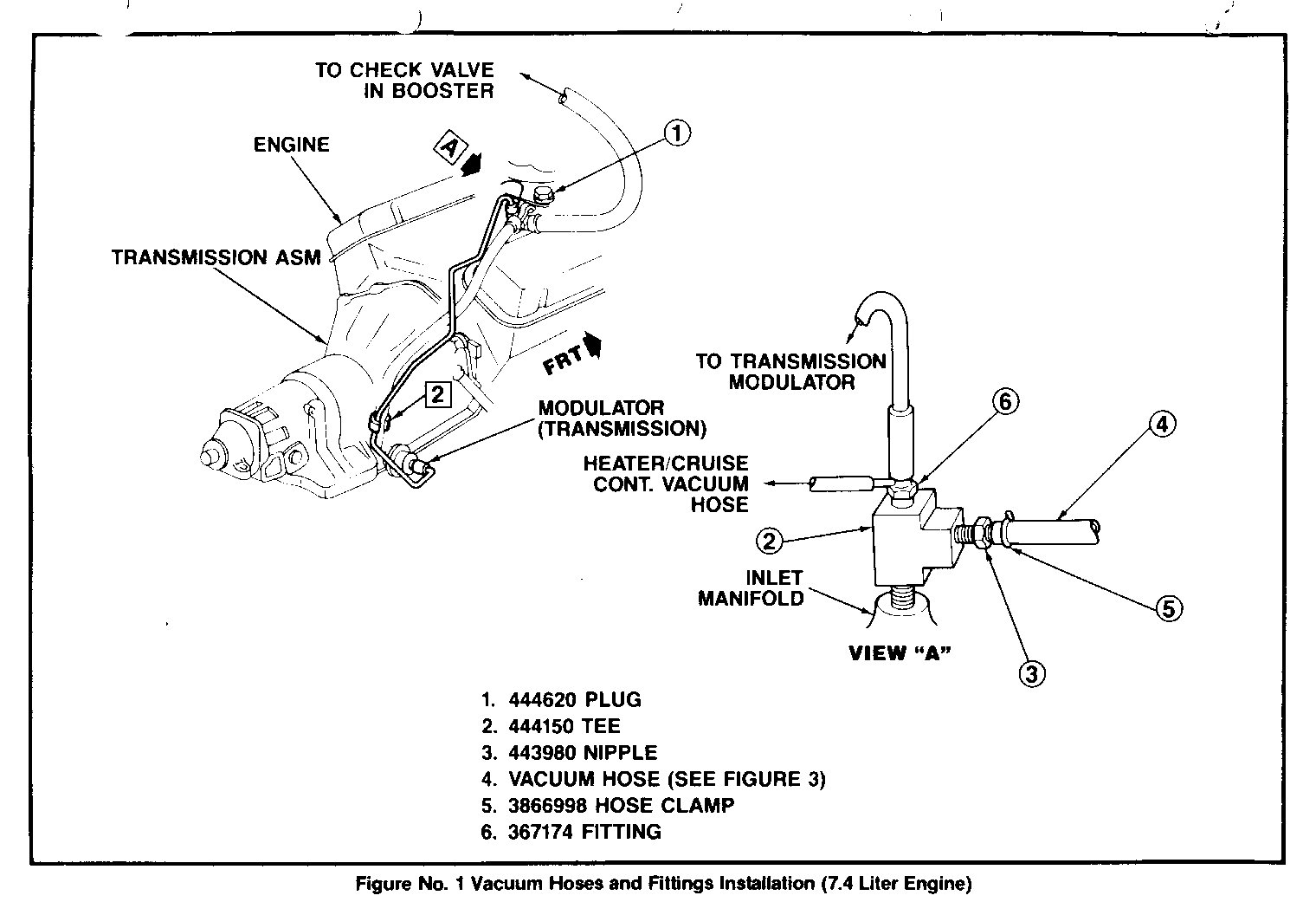
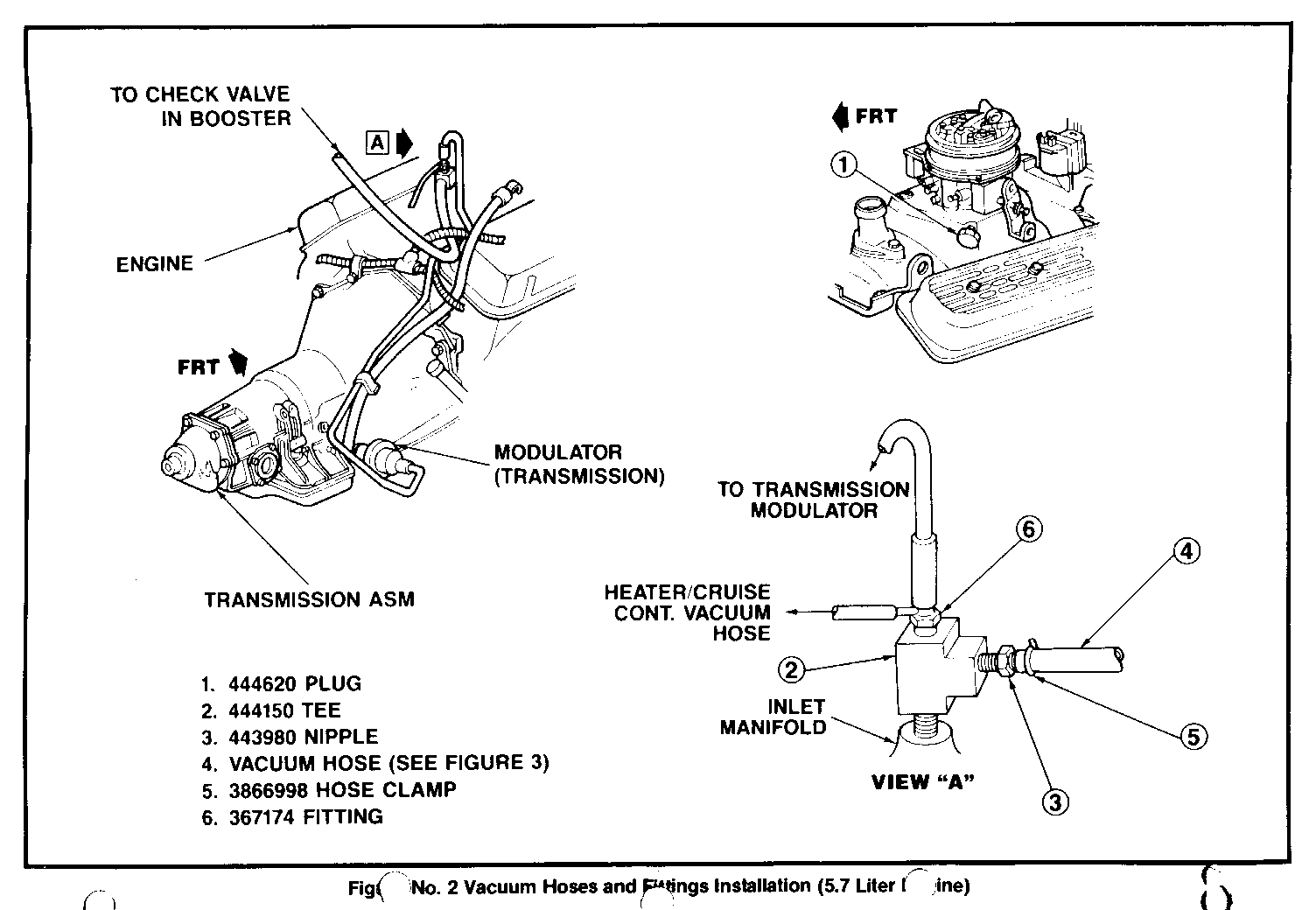
1. Install pipe plug (1) in TBI adapter (See Figure 1 for the 7.4L engine and Figure 2 for the 5.7L engine). Torque to 11- 14 Nm.
2. Install pipe tee (2) in inlet manifold. Torque to 11 Nm minimum (See Figure 1 or Figure 2).
3. Install nipple (3) in horizontal side of tee. Torque to 11-14 Nm.
4. Install vacuum fitting (6) into vacuum tee. Torque to 11 Nm minimum.
5. Install heater/vent vacuum hose to side nipple on fitting and transmission modulator pipe onto top nipple of fitting. If vehicle is not equipped with cruise control or A/C, plug side nipple on fitting.
6. Check to see that air cleaner clears top of the modulator pipe. It may be necessary to force fitting (6 on Figure 1 and Figure 2), deeper into tee or reshape modulator pipe slightly. If interference still exists, modulator pipe is not fully seated into fitting (6). Remove hose sleeving from modulator pipe and check aligniment of pipe to fitting. Bend pipe slightly to collect alignment. Lubricate hose sleeve with silicone spray and install back on modulator pipe. Push sleeve as high as possible and insert modulator pipe back into fitting. Slide hose sleeve back down to proper position. Recheck for proper clearance.
7. Attach 15/32 ID vacuum bose (4) to nipple on tee (2) and secure with hose clamp (5) about V4 inch from hex on nipple.
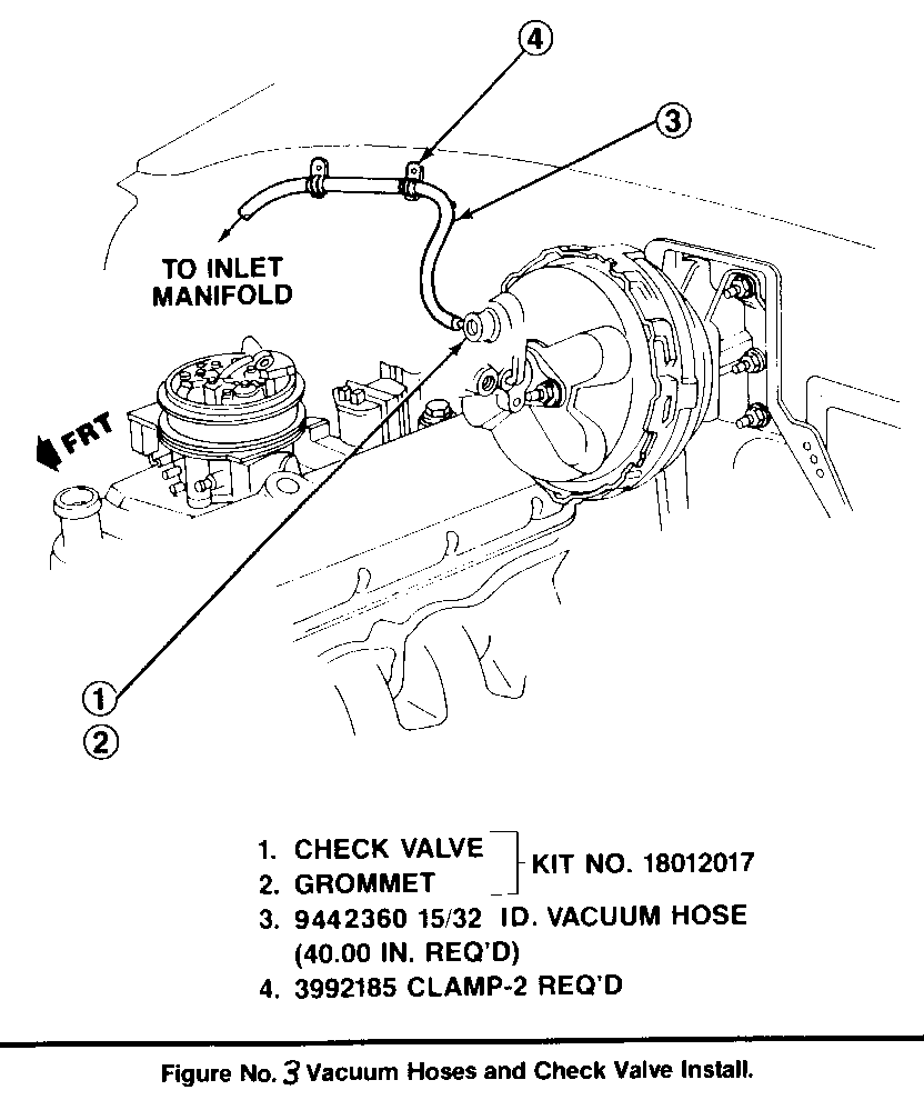
8. Route hose under map sensor and wiring harness and over valve rocker cover Carefully route hose over distributor and clip (4) in 2 places on vertical surface of cowl above dis- tributor (see Figure No. 3). Adjust hose carefully so it will not kink or rub against cowl or other parts witb engine movements.
9. It may be necessary to rotate the tee in the inlet manifold to help route hose properly.
10. Install new grommet (2) and check valve (1) in booster Some units may require loosening the master cylinder to install tbe check valve.
11. Attach 15/32 ID vacuum hose (3) to check valve.
12. Reinstall air cleanen
13. Reconnect battery ground cable.
Notice: Start engine and check for proper braking action before road testing.
Labor time to perform this procedure is:
.7 hr. - for vehicles with 5.7L engine (RPO L05 and LT9) .9 hr. - for vehicles with 7.4L engine (RPO L19 and E8)
In both cases, use Labor Operation number T7515.
Parts are currenty available from GMSPO.
Parts List Quantity Part Number ---------- -------- ----------- Power Brake Kit 1 15624666
Notice: Kit Consists of:
Pipe Plug 1 444620 Pipe Tee 1 444150 Nipple 1 443980 Hose Clamp 1 3866998 Fitting Vacuum Ho se 1 367174 Check Valve Kit 1 18012017 Clamp Hose 2 3992185 Hose 1 9442360 Instruction 1 15624667


General Motors bulletins are intended for use by professional technicians, not a "do-it-yourselfer". They are written to inform those technicians of conditions that may occur on some vehicles, or to provide information that could assist in the proper service of a vehicle. Properly trained technicians have the equipment, tools, safety instructions and know-how to do a job properly and safely. If a condition is described, do not assume that the bulletin applies to your vehicle, or that your vehicle will have that condition. See a General Motors dealer servicing your brand of General Motors vehicle for information on whether your vehicle may benefit from the information.
