FRONT DRIVE AXLE SEAL REPL. (SERVICE INFORMATION)

SUBJECT: FRONT DRIVE AXLE SEAL REPLACEMENT (SERVICE INFORMATION)
MODELS: 1988-1991 K-TRUCK
The front drive axle removal and replacement procedures have been updated in the 1992 Sierra, Yukon, Suburban Service Manual (X-9231) Section 4C-6. These procedures apply to the removal and replacement of front drive axles for any 1988-92 K truck.
Front axle inner (tripot) seal and outer (C/V) seal replacement procedures are updated in the following Service Manual Update (SMU):
X-9174 Issue No. 14, November, 1991
SUBJECT: SWAGE CLAMP AND BOOT REPLACEMENT
MODELS: 1988-92 K-MODEL TRUCK
Important highlights of the SMU include:
- Cleaning of the axle shaft grooves and proper location of the seal on the axle shaft grooves.
- Cleaning of all internal components and use of the premeasured grease packet.
- Proper inboard seal installation using the convolute retainer included in the seal kit.
- Proper inboard seal installation dimensions.
- Proper use of the swage clamp special tool J 36652.
SERVICE PARTS INFORMATION:
Part Number Model Description ------ ----- ----------- 26020732 1988-92 K1, K2 Seal Kit, C/V (7,200 GVWR) (Outer)
26018970 1988-92 K1, K2 Seal Kit, Tripot (7,200 GVWR) (Inner)
26020729 1988-92 K2 Seal Kit, C/V (8,600 GVWR), K3 (Outer)
260189631 1988-92 K2 Seal Kit, Tripot (8,600 GVWR), K3 (Inner)
Parts are currently available from GMSPO.
WARRANTY INFORMATION:
For vehicles repaired under warranty, refer to appropriate Labor Time Guide for Labor Times.
SUBJECT: SWAGE CLAMP AND BOOT REPLACEMENT
MODELS: 1988-92 K-MODEL TRUCK
This information updates the information found under DRIVE AXLE ASSEMBLY beginning on page 4C4-22 of the 1992 Light Duty Unit Repair Manual, X-9237 or ST 333-92. It applies equally to previous year vehicles.
OUTER JOINT SEAL REPLACEMENT
Remove or Disconnect (Figures 1 through 5)
Tools Required:
J 8059 Snap Ring Pliers J 35910 Seal Clamp Tool J 36652 Swage Clamp Tool
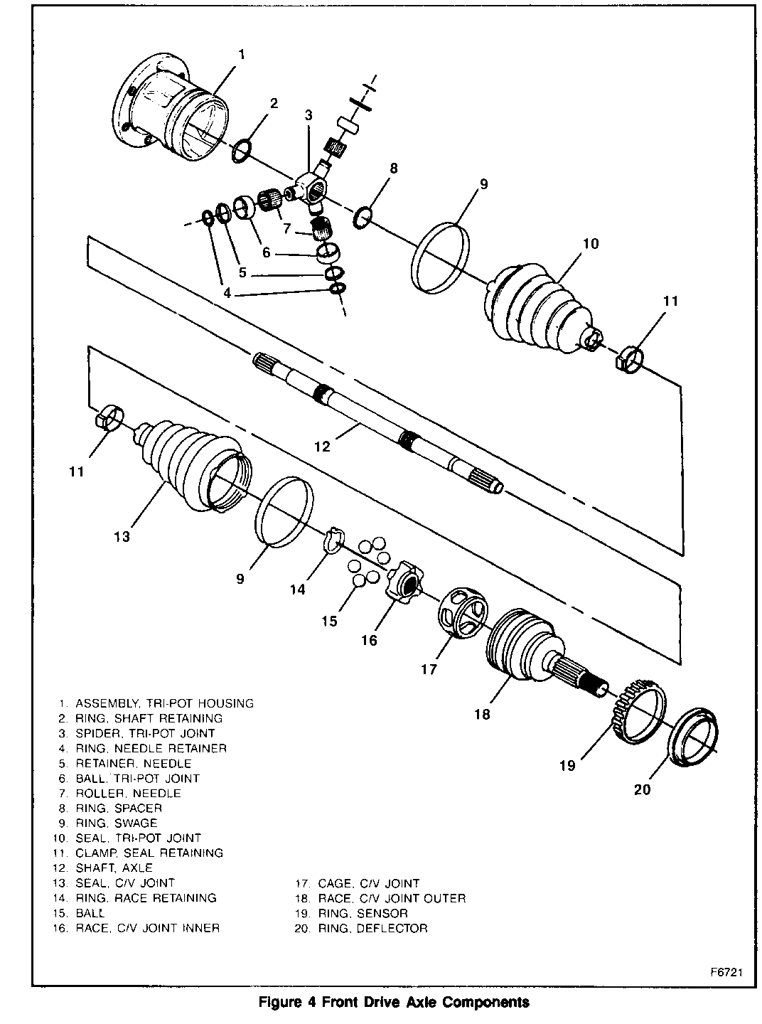
1. Large swage ring (9) from the C/V joint, using a chisel and discard.
Important
- Do not cut through the seal (13) and damage the sealing surface of C/V outer housing (18) with the chisel.
2. Small seal-retaining clamp (11) on axle shaft with a side cutter, and discard.
A. Separate the joint seal (13) from the C/V joint race (18) at large diameter and slide the seal away from joint along the axle shaft (12).
B. Wipe excess grease from face of C/V inner race (16).
C. Spread the ears on the race retaining ring (14) with J 8059 and remove the C/V joint assembly from the axle shaft (12).
3. Seal (13) from the axle shaft (12).
- Disassemble the joint and flush grease prior to installing the new seal. Refer to "Outer Joint Assembly Replacement."
Clean
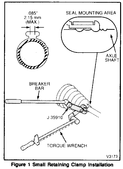
- Clean the shaft. If rust is present in the seal mounting area (grooves), wire brush this area (figure 1).
Install or Connect
1. Small seal-retaining clamp (11) on the neck of the new seal (13). Do not crimp.
A. Slide the seal (13) onto the axle shaft (12) and position the neck of the seal in the seal groove on the axle shaft.
B. Crimp the self retaining clamp (11) with J 35910 to 136 N.m (100 ft. lbs.) (figure 1).
- Inspect small retaining ring clamp gap dimension and compare with figure 1).
C. Place approximately half of the grease provided inside the seal (13) and repack the C/V with the remaining grease.
2. Swage ring (9).
A. Pinch by hand slightly to distort into an oval shape and slide onto large diameter of the seal (13).
B. With the boot compressed, push the joint onto the shaft. A "click" will indicate seating of the inner race snap ring in the axle shaft groove. Pull the CV joint to verify engagement.
C. Slide large diameter of the seal (13) with the large swage ring (9) in place over the outside of the C/V joint race (18) and locate the seal lip in the housing groove.
Important
- The seal (13) must not be dimpled, stretched or out of shape in any way. If the seal is not shaped correctly, carefully insert a thin flat blunt tool (no sharp edges) between the large seal opening and the outer race (18) at maximum clearance of oval ring (9) to release the air. Shape the seal by hand and remove the tool.
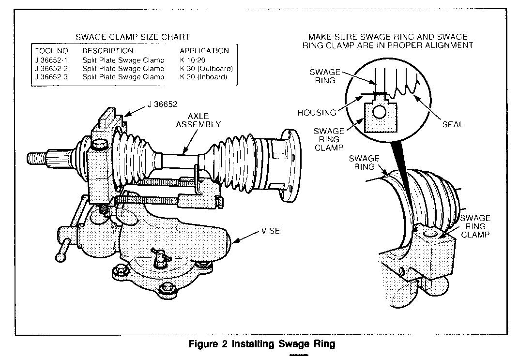
D. Refer to the chart in figure 2 and select the correct size swage clamp tool J 36652.
E. Mount the proper size swage clamp tool in the vise and proceed as follows:
a. Position the outboard end of the axle assembly in the tool.
b. Place the top half of the tool on the lower half of the tool and check for proper alignment (figure 2).
c. Insert the bolts and tighten by hand until snug.
Important
- Make sure the seal (13), housing (18), and swage ring (9) all remain in alignment (figure 2).
d. Continue to tighten each bolt 180 degrees at a time alternately until both sides are bottomed.
F. Remove the axle assembly from the tool.
INNER TRI-POT SEAL REPLACEMENT
Remove or Disconnect (Figures 1 through 4)
Tools Required:
J 8059 Snap Ring Pliers J 35910 Seal Clamp Tool J 36652 Swage Clamp Tool
1. Large swage ring (9) from the in-pot joint, using a chisel, and discard.
Important
- Do not cut through the seal (10) with the chisel and damage the sealing surface of the tri-pot outer housing (1).
2. Small seal-retaining clamp (11) from the axle shaft (12) with a side cutter, and discard.
- Separate seal (10) from the tri-pot housing (1) at the large diameter and slide the seal away from the joint along the axle shaft (12).
3. Tri-pot housing (1) from the spider (3) and shaft.
- Spread the spacer ring (8) with J 8059 and slide the spacer ring and the tri-pot spider (3) back on the axle shaft (1 2).
4. Shaft retaining ring (2) from the groove on the axle shaft (12) and slide the spider assembly off the shaft.
Important
- Handle the tri-pot spider assembly with care or the tri-pot balls and needle rollers may separate from the spider trunions.
5. Remove the spacer ring (8) and the seal (10) from the axle shaft (12).
6. Flush grease from the housing.
Clean
- Clean the shaft. If rust if present in the seal mounting area (grooves), wire brush this area (figure 1).
Install or Connect
1. Small seal-retaining clamp (1 1) on the neck of the seal (1 0).
- Do not crimp.
2. Slide the seal (10) onto the shaft (12) and position the neck of the seal in the seal groove on the axle shaft.
A. Crimp seal retaining clamp (1 1) with J 35910 to 136 N.m (100 ft. lbs.)
B. Inspect clamp ear gap dimension and compare to figure 1.
3. Spacer ring (8) on the front axle shaft (12) and beyond the second groove as shown.
- Slide the tri-pot spider assembly against the spacer ring (8) and the shaft (12).
Important
- Be sure that the counterbored face of the tri-pot spider (3) faces the end of the shaft (12).
4. Shaft retaining ring (2) in the groove of the axle shaft (12) with J 8059.
5. Slide the tri-pot spider (3) towards the end of the shaft (1 2) and reseat the spacer ring (8) in the groove on the axle.
A. Place approximately half of the grease provided in the seal (10) and use the remainder to repack the tri-pot housing (1).
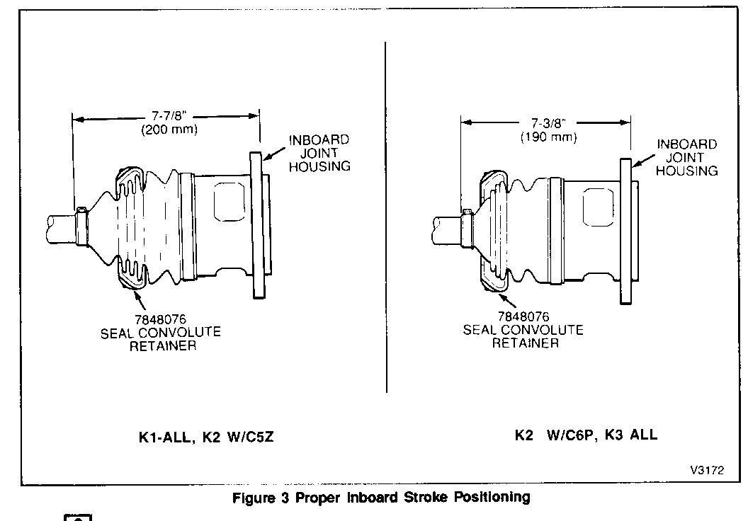
6. Position the Seal Convolute Retainer (supplied with service kit) over the boot and assemble the joint to the dimension shown in figure 3.
7. Slide the tri-pot housing (1) over the tri-pot spider assembly on the shaft (12).
8. Slide the large diameter of the seal (10) with the large swage ring (9) in place over the out- side of the tri-pot housing (1) and locate the seal lip in the housing groove.
Important
- Seal length must be at dimension shown in figure 3.
- The seal (13) must not be dimpled, stretched or out of shape in any way. If the seal is not shaped correctly, slide the swage ring (9) off the seal and onto the housing (1). Carefully insert a thin, flat, blunt tool (no sharp edges) between the seal opening and the housing to release the air. Shape the seal properly by hand and remove the tool.
9. Return the swage ring (9) to position on the seal (10).
- Refer to the chart in figure 2 and select the proper size swage clamp tool J 36652.
10. Mount the swage clamp tool in the vise and proceed as follows:
A Position the inboard end of the axle assembly in the tool.
B. Place the top half of the proper size tool on the lower half of tool and check for proper alignment and dimension (figure 2).
C. Insert the bolts and tighten by hand until snug.
Important
- Make sure that the seal (10), housing (1) and swage ring (9) all remain in alignment (figure 2).
D. Continue to tighten each bolt 180 degrees at a time, alternating until both sides are bottomed.
11. Remove the axle assembly from the tool.


General Motors bulletins are intended for use by professional technicians, not a "do-it-yourselfer". They are written to inform those technicians of conditions that may occur on some vehicles, or to provide information that could assist in the proper service of a vehicle. Properly trained technicians have the equipment, tools, safety instructions and know-how to do a job properly and safely. If a condition is described, do not assume that the bulletin applies to your vehicle, or that your vehicle will have that condition. See a General Motors dealer servicing your brand of General Motors vehicle for information on whether your vehicle may benefit from the information.
