Starter Disassemble SD-260 Solenoid
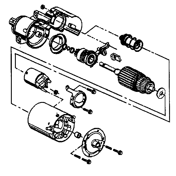
- Clean the outside of the starter housing.
- Make scribe marks to show the relationship of the drive end frame,
frame and field assembly, and the end frame to aid in assembly.
- Note the position of the through-bolts.
- Models with solenoid shield:
| • | Solenoid shield nuts from the solenoid clamp screws. |
| • | Shield from the solenoid. |
| • | Motor lead attaching nut and lead from the solenoid. |
| • | Solenoid clamp attaching screws, clamp, and solenoid from the
frame assembly. |
Starter Disassemble SD-260 Frame and Field

- Disassemble the through bolts from the end frame.
- Disassemble the end frame.
- Disassemble the brake washer from the armature assembly.
- Disassemble the frame and field from the armature/drive and frame
assembly.
Starter Disassemble SD-260 Drive End Frame
- Disassemble the plug from the drive end frame assembly.

- Disassemble the armature with the drive
assembly, shift lever, plunger and return spring from the drive end frame.
- Disassemble the return spring from the plunger.
- Disassemble the plunger from the shift lever.
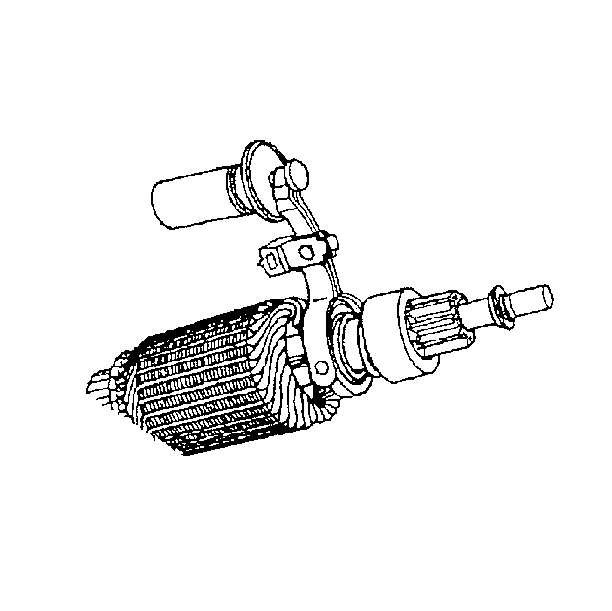
- Disassemble the shift lever from the drive assembly by spreading the lever
arms slightly to snap them off the mating buttons on the drive collar.
- Disassemble the drive assembly from the armature shaft in the
following way:
| • | Remove the thrust collar away from the armature shaft. |
| • | Drive the pinion stop collar away from the pinion stop retainer
ring by sliding a metal cylinder onto the armature shaft. Strike the metal
cylinder against the stop collar with a hammer. |
| • | Spread the pinion stop retainer ring to remove it from the groove
in the armature shaft. Discard the old ring. The retainer ring must be replaced. |
| • | Slide the stop collar and the drive assembly off the armature
shaft. |
Starter Disassemble 28-MT Frame and Field
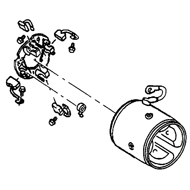
- Disassemble the insulated brush screws. Move the brush holder assembly with
the brushes slightly away from the frame and the field assembly to reach across
with a screwdriver and remove the screws.
- Disassemble the frame and the field assembly.
- Disassemble the grounded brush screws.
- Disassemble the brushes if they need replacement.
- Disassemble the brush springs if they need replacement. Grasp
the brush end of each brush spring with needle nose pliers. Twist the spring
end away from the brush and remove the brush.
Starter Disassemble 28-MT Reduction and Drive
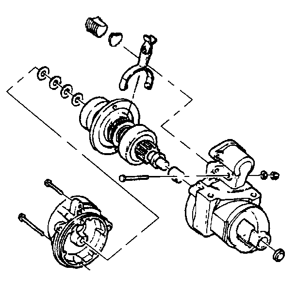
- Disassemble the housing bolts.
- Disassemble the armature support bracket.
Important: Washers may stick to the bracket or to the driveshaft and the clutch
group as the bracket is removed. In either case, note the position and number
of each of these washers.
- Disassemble the washers.
- Disassemble the drive housing plug and plate. Pry out the housing
plug with a large flat-bladed tool.
- Disassemble the shift lever nut, the washer and the screw.
- Disassemble the shift lever and driveshaft and clutch group from
the drive housing together, then separate them. Do not remove the bushing
plug or the bushing from the drive housing unless replacement is necessary.
Starter Disassemble 28-MT Driveshaft and Clutch
Disassembly of the driveshaft and clutch group is not required
unless it is necessary to clean, inspect, or replace one or more parts of
the group separately.
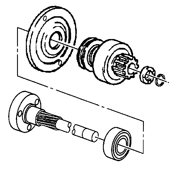
- Disassemble the stop rings and pinion stop.
- Position the driveshaft and clutch group on a work bench with
the internal gear end down.
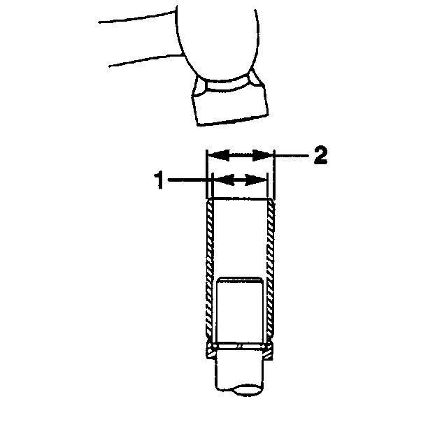
- Fabricate a tube approximately 22 mm wide (2). Drive the pinion stop
toward the clutch drive assembly until it clears the stop rings.
- Pry the stop rings out of the driveshaft groove and slide them
off the end of the shaft. Do not scratch the driveshaft.
- Inspect the edges of the shaft groove for burrs that may have
been formed through repeated cranking cycles. These burrs may make removal
of the pinion stop and clutch drive assembly difficult.
- Slide the pinion stop off the driveshaft. Discard the old pinion
stop and stop rings. New parts must be used at assembly.
- Disassemble the driveshaft support from the driveshaft. Do not
remove the bearing from the driveshaft unless replacement is required.


