Tools Required
| • | J 5239 Connecting Rod Guide Tool |
| • | J 8037 Piston Ring Compressor |
In order to determine the correct replacement bearing size, the bearing clearance must be measured accurately. Either the micrometer or plastic gauge method may be used, however, the micrometer method gives more reliable results and is preferred. Refer to Crankshaft and Bearing Cleaning and Inspection for the micrometer method.
Notice: Do not shim, scrape, or file bearing inserts. Do not touch the bearing surface of the insert with bare fingers. Skin oil and acids will etch the bearing surface.
- Install connecting rod bearings to the connecting rods and connecting rod caps.
- Lubricate the cylinder walls lightly with engine oil.
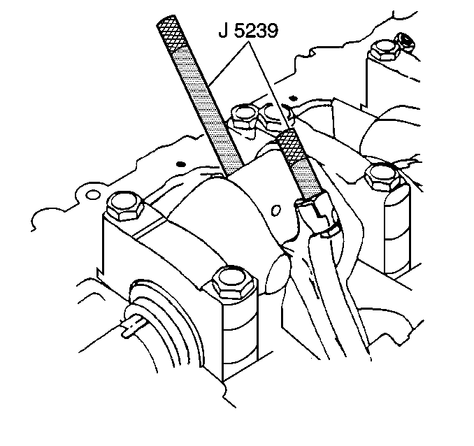
- With the connecting rod cap removed, install the J 5239 onto the connecting rod bolts.
- Align the piston ring end gaps.
- Lubricate the piston and the rings with engine oil.
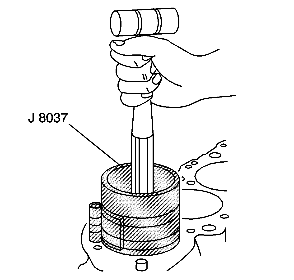
- Without disturbing the ring end gap location, install the J 8037 over the piston and the ring assembly.
- Compress the piston rings.
- Ensure that the dimple faces the front of the block.
- Install the piston and the connecting rod to the proper bore.
- Use a hammer handle to lightly tap the piston down into the cylinder bore.
- While tapping the piston into the bore, guide the connecting rod into position on the crankpin, using the J 5239 .
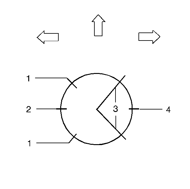
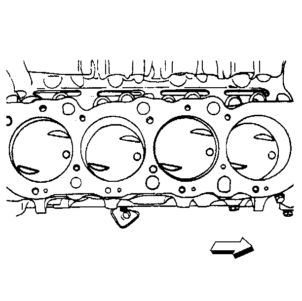
Important: Each connecting rod and bearing cap should be marked for proper location and orientation. Cylinder 1, 3, 5 and 7 are the right bank and 2, 4, 6, and 8 are the left bank (when viewed from the front of the engine). The numbers on the connecting rod and bearing cap must be on the same side when installed in the cylinder bore. If a connecting rod is ever transposed from one block or cylinder to another, new connecting rod bearings should be fitted and the connecting rod should be numbered to correspond with the new cylinder number.
The connecting rod bearings are of the precision insert type and do not use shims for adjustment. If the clearances are excessive, the new upper and the lower bearings will be required. The service bearings are available in the standard size and an undersize.
| • | 0.001 in |
| • | 0.002 in |
| • | 0.010 in |
| • | 0.020 in |
The selective fitting of the connecting rod bearings are necessary in production in order to obtain close tolerances. For this reason, you may use one-half of a standard connecting rod bearing with one-half of a undersize connecting rod bearing.
Plastic Gauge Method
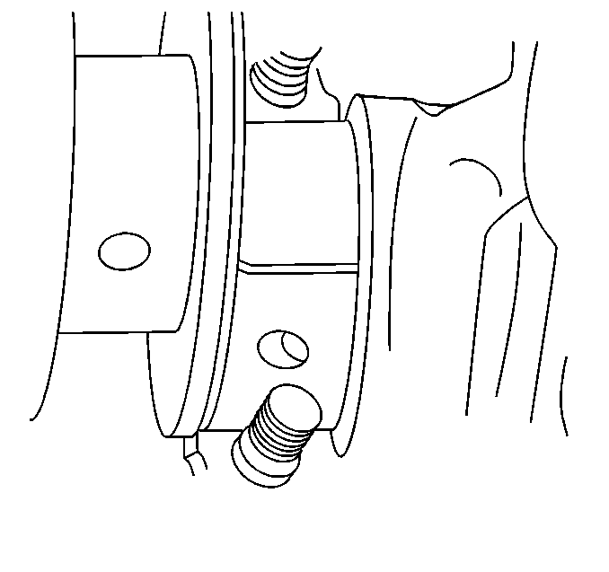
- Install the gauging plastic on the crankpin perpendicular to the connecting rod bearing.
- Install the connecting rod cap and the connecting rod nuts.
- Remove the connecting rod nuts and the connecting rod cap.
- Measure gauging plastic.
- If the flattened gauging plastic tapers toward the middle or the ends, there is a difference in clearance indicating taper, low spot or other irregularity of the bearing or the crankpin.
- Normally the crankpin bearing journals wear evenly and are not out-of-round. However, if a bearing is being fitted to an out-of-round 0.0254 mm (0.001 in maximum) journal, be sure to fit to the maximum diameter of the journal. If the bearing is fitted to the minimum diameter and the journal is excessively out-of-round, the interference between the bearing and the journal will result in rapid bearing failure.
- If the bearing clearance is within specifications, the bearing is satisfactory. If the clearance is not within specifications, replace the bearing. Always replace both the upper and the lower bearings as a unit.
- A standard or undersize bearing combination may result in the proper clearance. If the proper bearing clearance cannot be achieved using the standard or the undersize bearings, it will be necessary to replace or repair the crankshaft.
- Remove the flattened gauging plastic.
- Install and measure the remaining connecting rods.
Tighten
Tighten the connecting rod nuts to 61 N·m (45 lb ft).
Notice: Use the correct fastener in the correct location. Replacement fasteners must be the correct part number for that application. Fasteners requiring replacement or fasteners requiring the use of thread locking compound or sealant are identified in the service procedure. Do not use paints, lubricants, or corrosion inhibitors on fasteners or fastener joint surfaces unless specified. These coatings affect fastener torque and joint clamping force and may damage the fastener. Use the correct tightening sequence and specifications when installing fasteners in order to avoid damage to parts and systems.
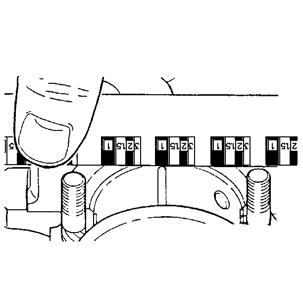
| • | Gauging plastic may adhere to either the connecting rod bearing or crankpin. |
| • | Without removing the gauging plastic, measure the compressed width at the widest point using a graduated scale provided on the gauging plastic envelope. |
Final Connecting Rod Bearing Installation Procedure
- Coat the connecting rod bearings with clean engine oil.
- Coat the crankpin with clean engine oil.
- Install the connecting rod cap with the bearing and the connecting rod nuts.
Tighten
Tighten the connecting rod bolt nuts to 61 N·m (45 lb ft).
Notice: Use the correct fastener in the correct location. Replacement fasteners must be the correct part number for that application. Fasteners requiring replacement or fasteners requiring the use of thread locking compound or sealant are identified in the service procedure. Do not use paints, lubricants, or corrosion inhibitors on fasteners or fastener joint surfaces unless specified. These coatings affect fastener torque and joint clamping force and may damage the fastener. Use the correct tightening sequence and specifications when installing fasteners in order to avoid damage to parts and systems.
