For 1990-2009 cars only
Cleaning Procedure
- Clean the sealing material from the mating surfaces.
- Boil the cylinder block in caustic solution.
- Flush the cylinder block with clean water or steam.
- Clean the cylinder bores.
- Clean the oil galleries and the passages.
- Clean the scale deposits from the coolant passages.
- After cleaning the engine block, spray or wipe the cylinder bores and the machined surfaces with clean engine oil.
Inspection Procedure
- Inspect the valve lifter bores for deep scratches and varnish deposits.
- Check the block for cracks.
- Inspect the cylinder walls for scoring.
- Inspect the coolant jackets.
- Inspect the crankshaft bearing webs.
- Inspect the engine mount bosses.
- Inspect the crankshaft bearing bores and the crankshaft bearing caps.
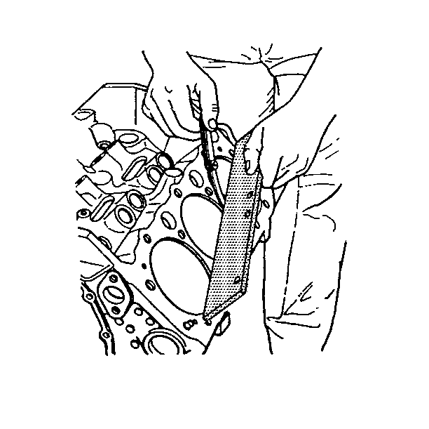
- Check cylinder head gasket surface for flatness using a straight edge and a feeler gauge. The surface must be flat within 0.10 mm (0.004 in).
| • | All crankshaft bearing bores must be round and uniform in inside diameter (ID) at all the bearing supports. |
| • | The area where the crankshaft bearings contact the crankshaft bearing bore must be smooth. |
| • | Note if a crankshaft bearing cap is damaged and requires replacement refer to Crankshaft and Bearing Cleaning and Inspection . |

Cylinder Bore Taper and Out-of-Round Measuring Procedure
Tools Required
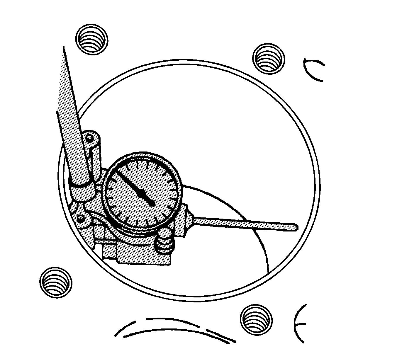
J 8087 Cylinder Bore Gauge
- Ensure that the cylinder bore tolerances are correct. Refer to Engine Mechanical Specifications
- Depress the plunger on the tool 7 mm (0.03 in) or until the tool enters the cylinder bore.
- Center the gauge in the cylinder. Turn the dial to zero.
- Carefully work the gauge up and down the cylinder in order to determine the taper and turn it to different points around the cylinder wall to determine the out-of-round condition.
Important: If one or more of the cylinder bores are rough, scored, or worn beyond limits, smooth or true up the damaged bores in order to fit new pistons.
Do not cut down oversize pistons in order to fit the cylinder bores, as this will destroy the surface treatment and affect the weight. Use the smallest possible oversize service pistons and hone the cylinder bores to size for the proper clearances.
Measure the bore both parallel to and at right angles to the engine centerline. Measure at the top, middle, and the bottom of the bore and note the readings.
