Tools Required
J 24086-C Piston
Pin Removal and Installation Set
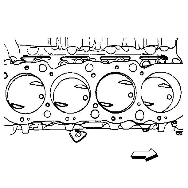
Important: Each connecting rod and connecting rod bearing cap must be marked, beginning
at the front of the engine. When viewed from the front of the engine, cylinders
1, 3, 5, and 7 are the right bank. Cylinders 2, 4, 6, and 8 are the left bank.
The numbers on the connecting and the bearing cap must be on the same side
when installed in the cylinder bore. If a connecting rod is ever transposed
from one block or cylinder to another, the new connecting rod bearings must
be fitted and the connecting rods renumbered in order to correspond with the
new cylinder number. The connecting rod is not symmetrical and the outside
always faces the outside.
- Assemble the piston and the connecting rod as follows:
| 1.1. | Ensure that the alignment mark on the top of the piston faces
the front of the engine block. The connecting rod must be installed in the
correct orientation. |
| 1.2. | Lubricate the piston pin holes in the piston and the connecting
rod with engine oil. |
| 1.3. | Install the pin guide. |
Hold the piston and the connecting rod together. Use the proper pin
guide and refer to the manufacturer's instructions for proper use.
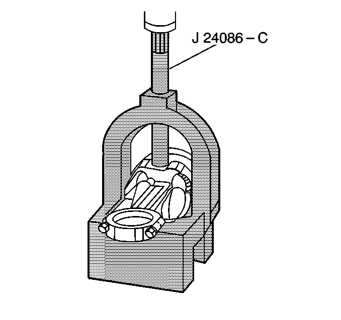
- Install the piston pin as follows:
| 2.1. | Insert the piston pin into the piston pin hole. |
| 2.3. | Adjust the piston pin installer to the correct length, using the
letter-number scale on the installer adjuster. |
Ensure the piston pin is pressed into the correct depth. Refer to the
manufacturer's instructions supplied with the tool for the proper setting.
| 2.4. | Lock the adjuster in place with the lock ring. |
| | Notice: After the J 24086-C installer hub bottoms on the support assembly,
DO NOT exceed 35,000 kPa (5,000 psi) or the tool may be damaged.
|
| 2.6. | Press the piston pin into place until the adjustable installer
bottoms in the J 24086-C
. |
| 2.7. | Remove the piston and the connecting rod assembly from the J 24086-C
. |
Check the piston for freedom of movement on the piston pin.
Piston Rings Installation Procedure
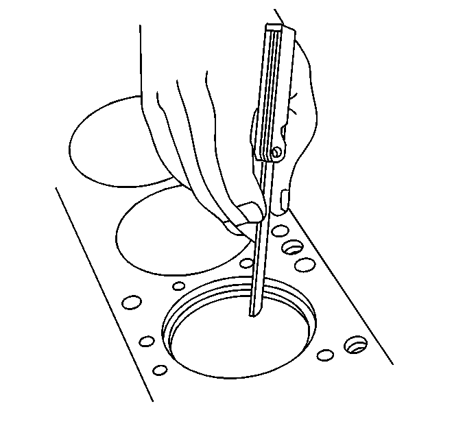
- Measure the ring end gap as follows:
| 1.1. | Select the rings comparable in size to the piston being used. |
| 1.2. | Slip the compression ring into the cylinder bore. |
| 1.3. | Use the piston to square ring in the cylinder wall. |
Insert the piston without rings upside down and guide the compression
ring into the cylinder bore until the ring is down about 38 mm (1.499 in)
below the ring travel.
| 1.5. | If the gap between the ends of the ring is not as specified, remove
the ring and try another for fit. |
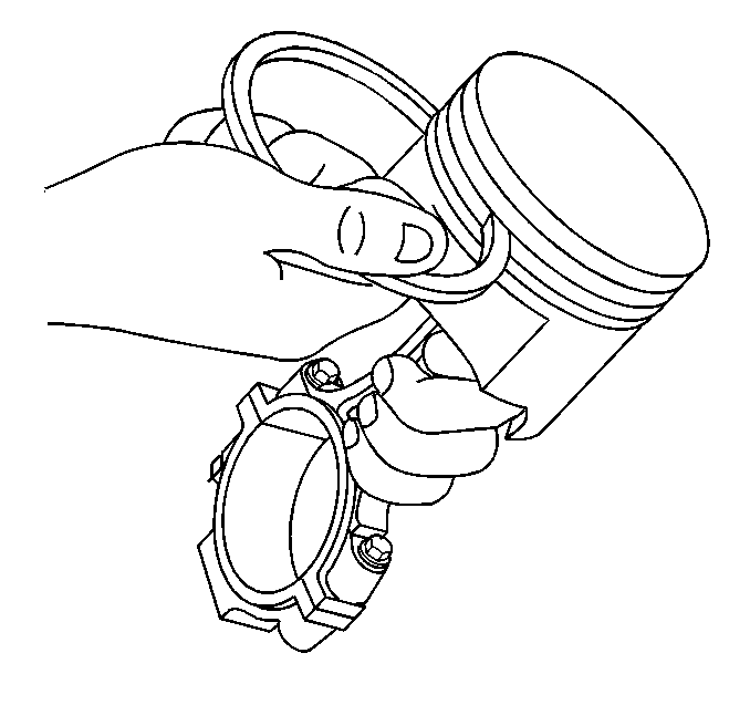
- Inspect the ring fit as follows:
| 2.1. | Fit each compression ring to the piston on which the compression
ring is to be used. |
| 2.2. | Slip the outer surface of the top and the second compression ring
into the respective piston ring groove in order to ensure that the compression
ring is free. |
| 2.3. | If binding occurs at any point, determine the cause. |
| 2.4. | If binding is caused by the ring groove, correct it by dressing
the groove with a fine cut file. |
| 2.5. | If the binding is caused by a distorted ring, try a new ring. |
Important: All compression rings are marked on the upper side of the ring.
When installing the compression rings, ensure that the marked side is
toward the top of the piston.
The oil rings are 3-piece assemblies, consisting of two rails
and an expander.
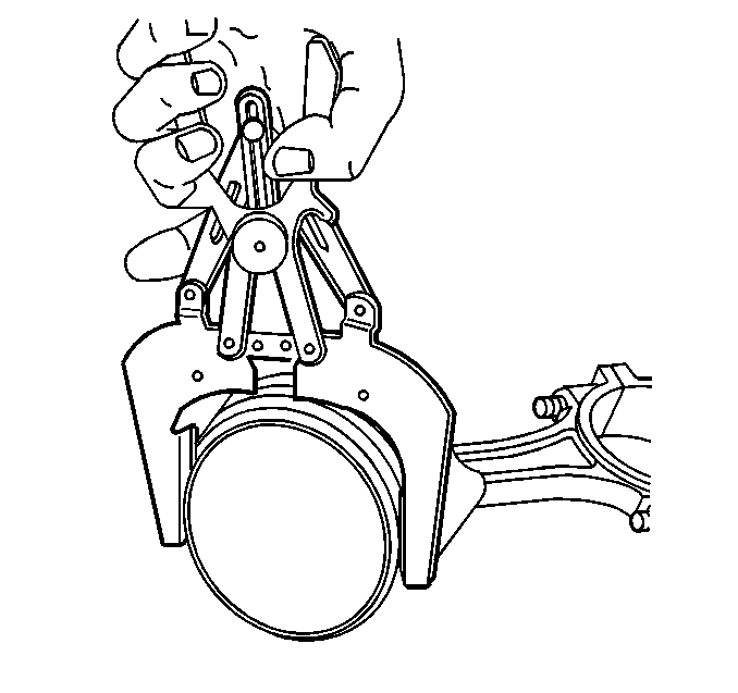
- Assemble the piston rings in the following order:
| 3.4. | The lower compression ring |
| 3.5. | The upper compression ring |
- Flex all of the rings in order to ensure that the rings are free.
- Determine the cause of any binding.
- If binding is caused by the ring groove, correct the binding by
dressing the groove with a fine cut file.
- If the binding is caused by a distorted ring, try a new ring.
| • | Rings gaps must be 180 degrees apart. |
| • | Rail gaps must be 180 degrees apart. |
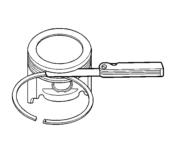
- Use the feeler gauge in order to measure ring to land clearance.


