Removal Procedure
Tools Required
J 39664 Manifold Cover Set
- Disconnect the negative battery cables. Refer to
Caution: Unless directed otherwise, the ignition and start switch must be in the OFF or LOCK position, and all electrical loads must be OFF before servicing any electrical component. Disconnect the negative battery cable to prevent an electrical spark should a tool or equipment come in contact with an exposed electrical terminal. Failure to follow these precautions may result in personal injury and/or damage to the vehicle or its components.
in General Information. - Remove the fuel filter. Refer to Engine Fuel.
- Drain the cooling system. Refer to Cooling and Radiator.
- Remove the thermostat bolts.
- Remove the fuel line return hose and the clips.
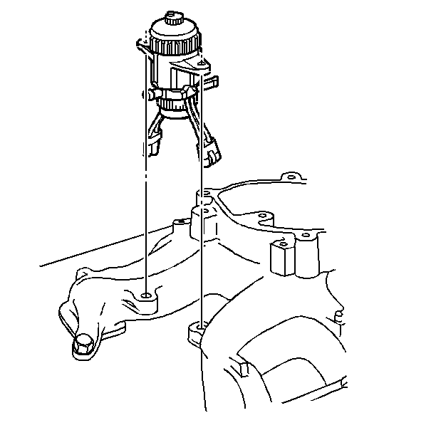
- For the L56 remove the EGR/Boost solenoids with the bracket from the intake manifold studs.
- For the L65 remove the Boost solenoids with the bracket from the intake manifold studs.
- Remove the heater hose bracket.
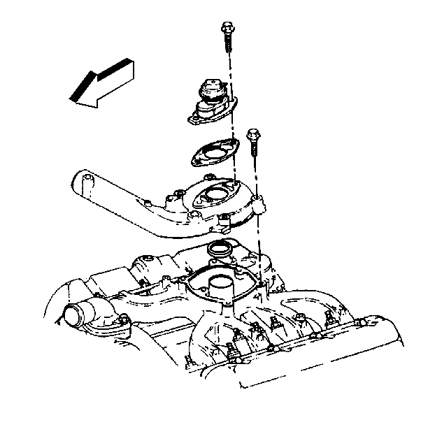
- Remove the vacuum hoses. at the EGR valve (L56 only).
- Remove the long pencil brace to the turbocharger.
- Remove the upper radiator hose.
- Remove the fuel filter assembly and the POE wiring harness bracket to the rear of the lower intake manifold.
- Remove the air intake hose from the turbocharger to the upper intake manifold.
- Remove the intake manifold studs and fuel line clips.
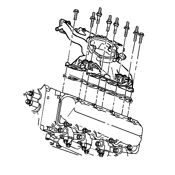
- Remove the intake manifold and the gasket.
- Clean the gasket surfaces on the intake manifold and the cylinder heads.
Important: Mark the placement of the studs in order to properly reinstall them.
Tighten
Tighten the fuel filter mount bolts to 42 N·m (31 lb ft).
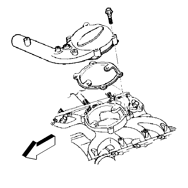
Important: In order to loosen the sealer, run a small screw driver (flat blade) between the hose and the upper intake manifold. Do not damage the hose.
Important: Mark the fuel line clips and brackets in order to insure proper reinstallation.
Important: If any further service work is to be done, cover the intake ports with the J 39664 .
Installation Procedure
- Remove the J 39664 from the intake ports before installing the gaskets.
- Install the intake manifold with new gaskets.
- Install the intake manifold studs and the fuel line clips.
- Install the upper intake manifold.
- For the L56 model, install the EGR tower gasket on the round center portion of the upper intake manifold.
- Slide the upper intake manifold into the turbocharger outlet hose.
- Apply the silicone sealant GM P/N 9985943, or equivalent, to the turbocharger outlet before you install the turbocharger outlet onto the upper intake manifold.
- Install the clamp for the turbocharger connector hose.
- Install the fuel line brackets and ground straps.
- Install the upper radiator hose.
- Install the long pencil brace to the turbo charger.
- Install the vacuum hoses.
- Install the heater hose bracket.
- Install the EGR/Boost solenoids with the bracket to the intake manifold studs.
- Install the fuel line return hose.
- Install the fuel filter and the bolts.
- Install the thermostat bolts.
- Connect the negative battery cables.
- Refill the engine coolant with the proper quantity and type of coolant. Refer to Cooling and Radiator.
Important: Be sure to use the correct gasket. The gaskets for the L56 models have openings for the EGR, the gaskets for the L65 models do not have openings.

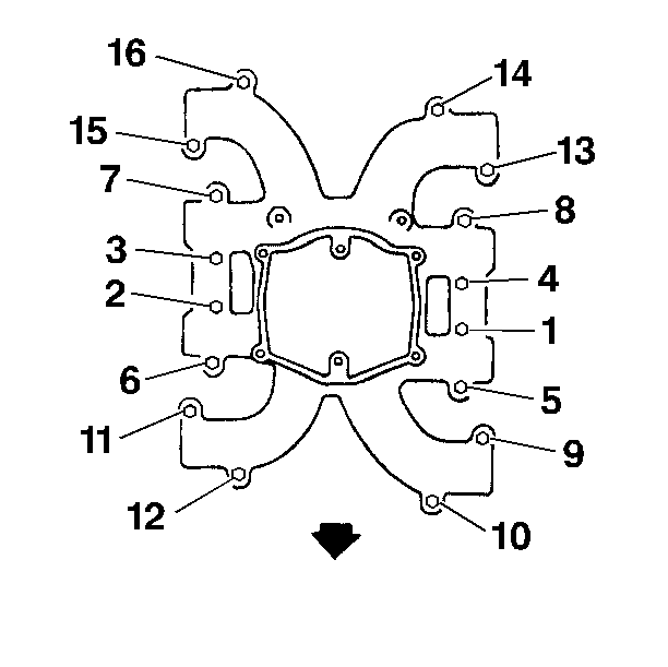
Important:
• There are four bolt/studs, numbers 9, 11, 13 and 15 exposed to
the crankcase, and should be sealed with teflon sealer. • Apply threadlocker GM P/N 12345493 to the threads of bolts and
studs numbers 1 through 8, 10, 12, 14, and 16.
Tighten
Tighten the intake manifold studs to 42 N·m (31 lb ft).
Notice: Use the correct fastener in the correct location. Replacement fasteners must be the correct part number for that application. Fasteners requiring replacement or fasteners requiring the use of thread locking compound or sealant are identified in the service procedure. Do not use paints, lubricants, or corrosion inhibitors on fasteners or fastener joint surfaces unless specified. These coatings affect fastener torque and joint clamping force and may damage the fastener. Use the correct tightening sequence and specifications when installing fasteners in order to avoid damage to parts and systems.

Tighten
Tighten the connector hose clamps to 6N·m (50 lb in).
Important: When replacing the upper intake manifold gasket for the L56, always replace the O-ring between the lower and upper intake manifolds. Failure to replace the O-ring will cause a driveability problem.

Tighten
Tighten the bolts to 42 N·m (31 lb ft).
