Cleaning Procedure
Caution: Some valves are under pressure. Cover the bores while removing the roll
pins or personal injury could result.
- Clean the control valve assembly thoroughly in clean solvent.
- Move the valve with a pick or small screwdriver in order to dislodge
any dirt or debris that may have accumulated.
- Air dry.
Disassemble Procedure
Important: Valves, springs, and bushings must be laid out on a clean surface in
the exact sequence they were removed.
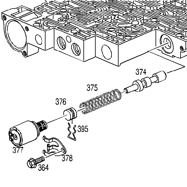
- Disassemble the pressure
control solenoid retainer bolt, retainer, and solenoid.
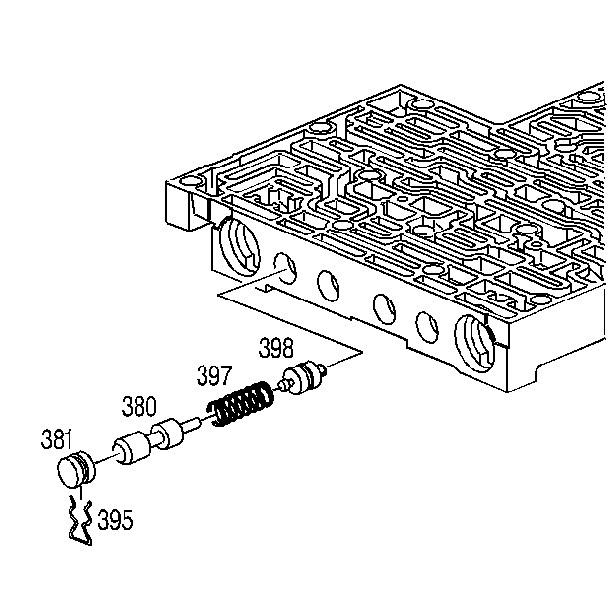
- Disassemble the bore plug
retainer clip, bore plug, and valve train.
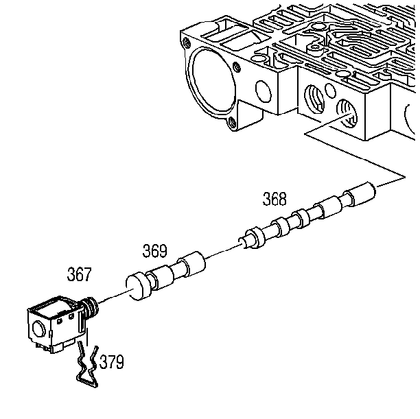
- Disassemble the 2-3 shift
solenoid retainer, solenoid, and valve train.
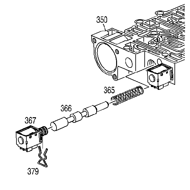
- Disassemble the 1-2 shift
solenoid retainer, solenoid, and valve train.
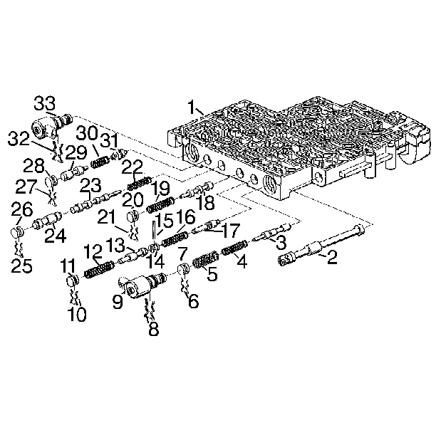
- Disassemble the accumulator
valve train retainer pin, more plug, and valve train.
- Disassemble the forward accumulator cover bolts and cover.
- Disassemble the forward accumulator spring, piston, and pin.
- Disassemble the low overrun valve spring and valve.
- Disassemble the retainer pin, bore plug, and the 3-2 control valve
train.
- Disassemble the manual valve.
- Disassemble the 3-2 control solenoid retainer clip and solenoid.
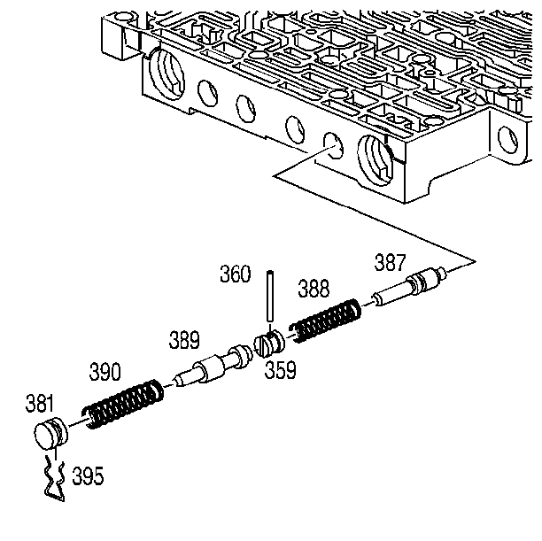
- Disassemble the bore plug
retainer, bore plug, and 3-2 control valve train.
- Disassemble the 3-2 downshift bore plug retainer, bore plug, and
valve train.
- Disassemble the reverse abuse more plug retainer pin, bore plug,
and valve train.
- Disassemble the 3-4 shift valve bore plug retainer, bore plug,
and valve train.
- Disassemble the torque converter clutch signal valve bore plug
retainer, bore plug, and valve.
- Clean all of the valves, springs, bushings, and control valve
body in clean solvent.
- Dry using compressed air.
Inspection Procedure
- Inspect all of the valves and bushings for the following conditions:
- Inspect the springs for damaged or distorted coils
- Inspect the valve body casting for the following conditions
| - | Interconnected oil passages |
| - | Damaged machined surfaces |
Assembly Procedure
- When assembling the control valve assembly, notice the position
of the valve lands and bushing passages.
- Position the pressure control solenoid so that the connectors
face outward.
Installation Procedure
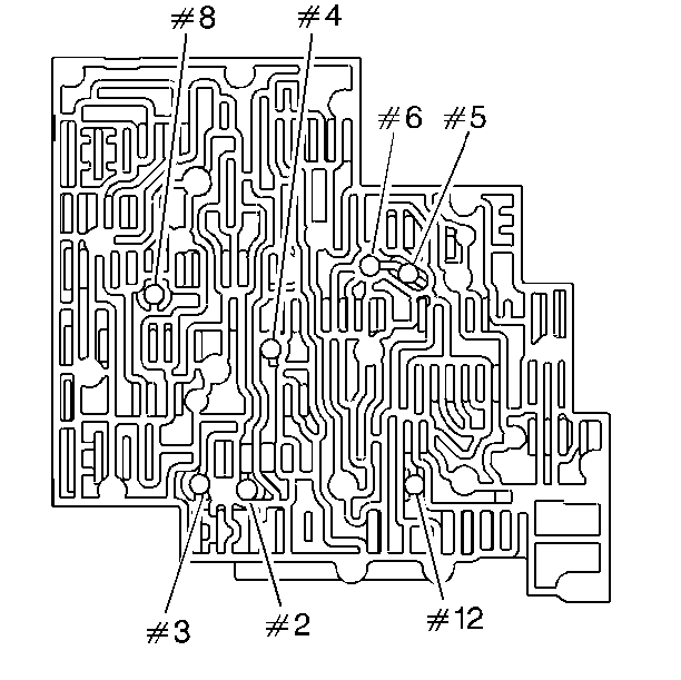
- Install the checkballs
into the valve body assembly. Retain with Transjel® or an equivalent.
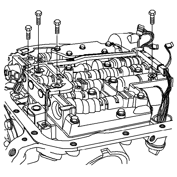
- Install the valve body
assembly.
| • | Connect the manual valve link to the inside detent lever. |
| • | Do not damage the screens when installing the valve body assembly. |
Notice: Torque valve body bolts in a spiral pattern starting from the center.
If the bolts are torqued at random, valve bores may be distorted and inhibit
valve operation.
- Install the wiring harness, manual spring assembly, pressure switch
assembly, and all of the remaining valve body bolts.

- Install the TCC solenoid
and bolts.
Tighten
Tighten the bolts to 11 N·m (97 lb in).
Notice: Use the correct fastener in the correct location. Replacement fasteners
must be the correct part number for that application. Fasteners requiring
replacement or fasteners requiring the use of thread locking compound or sealant
are identified in the service procedure. Do not use paints, lubricants, or
corrosion inhibitors on fasteners or fastener joint surfaces unless specified.
These coatings affect fastener torque and joint clamping force and may damage
the fastener. Use the correct tightening sequence and specifications when
installing fasteners in order to avoid damage to parts and systems.
- Install the wiring harness connections to the electrical components.
The pressure control solenoid has two different colored connectors. The black
connector should be installed on the tab farthest from the valve body.
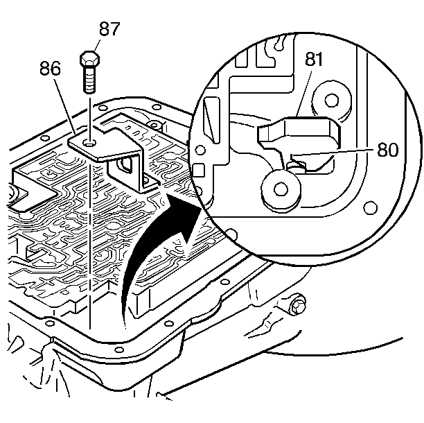
- Install the parking bracket.
Tighten
Tighten the bolts to 31 N·m (23 lb ft).
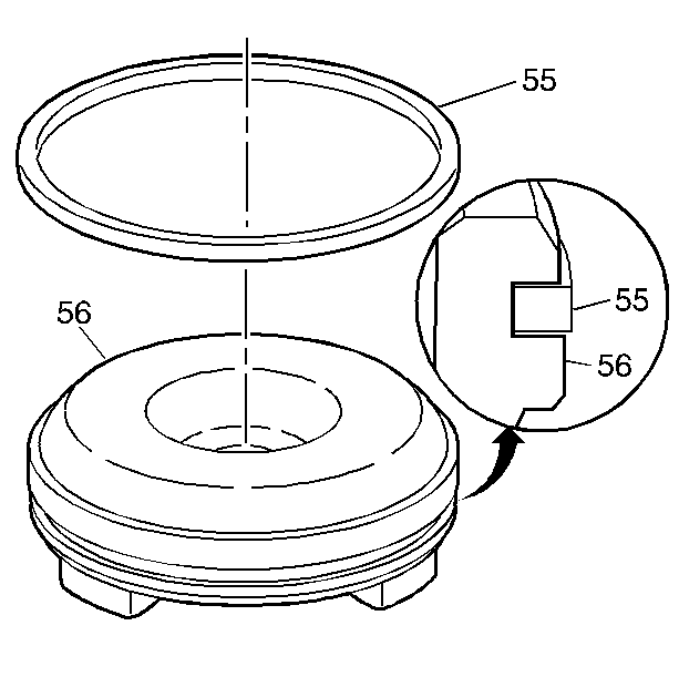
- Install the 1-2 accumulator
piston seal onto the 1-2 accumulator piston.
Important: The three legs on the piston must face toward the case when installed.
- Install the 1-2 accumulator piston into the 1-2 accumulator cover and
pin assembly.
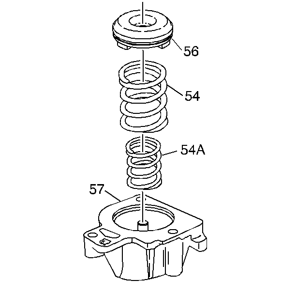
- The 1-2 accumulator spring
on the piston.
- The 1-2 accumulator cover and pin assembly onto the case.
Tighten
Tighten the bolts to 11 N·m (97 lb in).
- Install the new filter and gasket, pan bolts and new fluid.
- Lower the vehicle.
- Install the negative battery cable.
- Adjust the fluid level. Use Dexron® III Automatic Transmission
Fluid or the equivalent.
- Inspect for leaks.


