Removal Procedure
- Disconnect the battery negative cables from the batteries. Refer to Battery Cable in Engine Electrical.
- Remove the upper intake manifold from the lower intake manifold. Refer to Intake Manifold Replacement .
- Remove the lower intake manifold from the cylinder heads. Refer to Intake Manifold Replacement .
- Remove the valve rocker arm, shaft and push rod from the cylinder head. Refer to Valve Rocker Arm, Shaft, and Push Rod Replacement .
- Remove the cylinder head from the engine block. Refer to Cylinder Head Replacement .
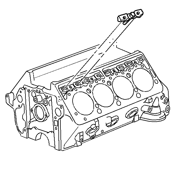
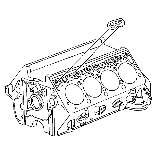
- Remove the valve lifter retainer and bolt from the engine block
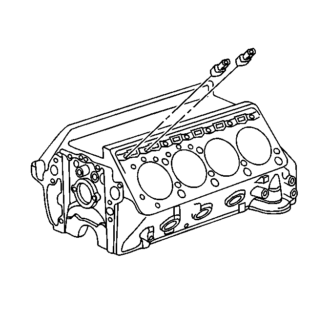
- Remove the valve lifter guide from the engine block.
- Remove the valve lifters from the engine block.
- Place the valve lifters, valve lifter guides, and retainer and bolt in a organizer rack


Important: Some engines will have both standard and 0.010 inch oversize valve lifters. The oversize valve lifter will have a "10" etched on the cast pad adjacent to the valve lifter bore and on the top rail of the cylinder case above the valve lifter.
Installation Procedure
- Apply a small amount of GM P/N 1052365 lubricant to the valve lifter roller bearings.
- Install the new valve lifters to the engine block.
- Install the valve lifter guide to the engine block.
- Install the valve lifter retainer and bolt to the engine block.
- Install the valve rocker arm, shaft, and push rod to the cylinder head. Refer to Valve Rocker Arm, Shaft, and Push Rod Replacement .
- Install the cylinder head assembly to the engine block. Refer to Cylinder Head Replacement .
- Install the lower intake manifold to the engine block. Refer to Intake Manifold Replacement .
- Install the upper intake manifold to the engine block. Refer to Intake Manifold Replacement .
- Connect the battery negative cables to the batteries. Refer to Battery Cable in Engine Electrical.


Important: After all the retainers are installed, turn the crankshaft by hand two full revolutions, to ensure free movement of the valve lifters in the guide. If the engine will not turn over by hand, one or more of the valve lifters may be binding in the guide.
Notice: Use the correct fastener in the correct location. Replacement fasteners must be the correct part number for that application. Fasteners requiring replacement or fasteners requiring the use of thread locking compound or sealant are identified in the service procedure. Do not use paints, lubricants, or corrosion inhibitors on fasteners or fastener joint surfaces unless specified. These coatings affect fastener torque and joint clamping force and may damage the fastener. Use the correct tightening sequence and specifications when installing fasteners in order to avoid damage to parts and systems.
Tighten
Tighten the bolts to 26 N·m (18 lb ft).
