- Coat the following components with clean engine oil:
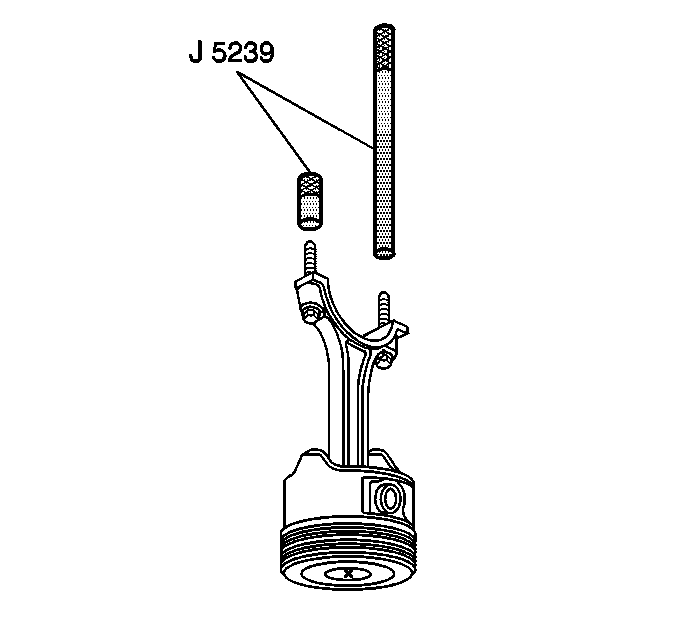
- Install the J 5239
onto the connecting rod.
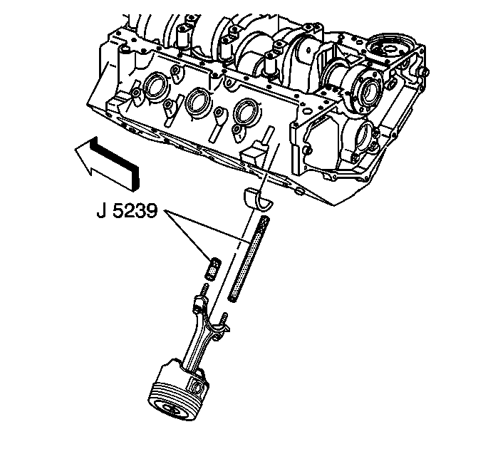
Notice: Do not shim, scrape, or file bearing inserts. Do not touch the bearing
surface of the insert with bare fingers. Skin oil and acids will etch the
bearing surface.
Important: The mark on the top of the piston must face the front of the engine
block. When assembled, the flanges on the connecting rod and cap should face
to the front of block on the left bank and to the rear of block on the right
bank.
- Install the piston, connecting rod and upper connecting rod bearing
through the top of the engine block using the J 5239
.
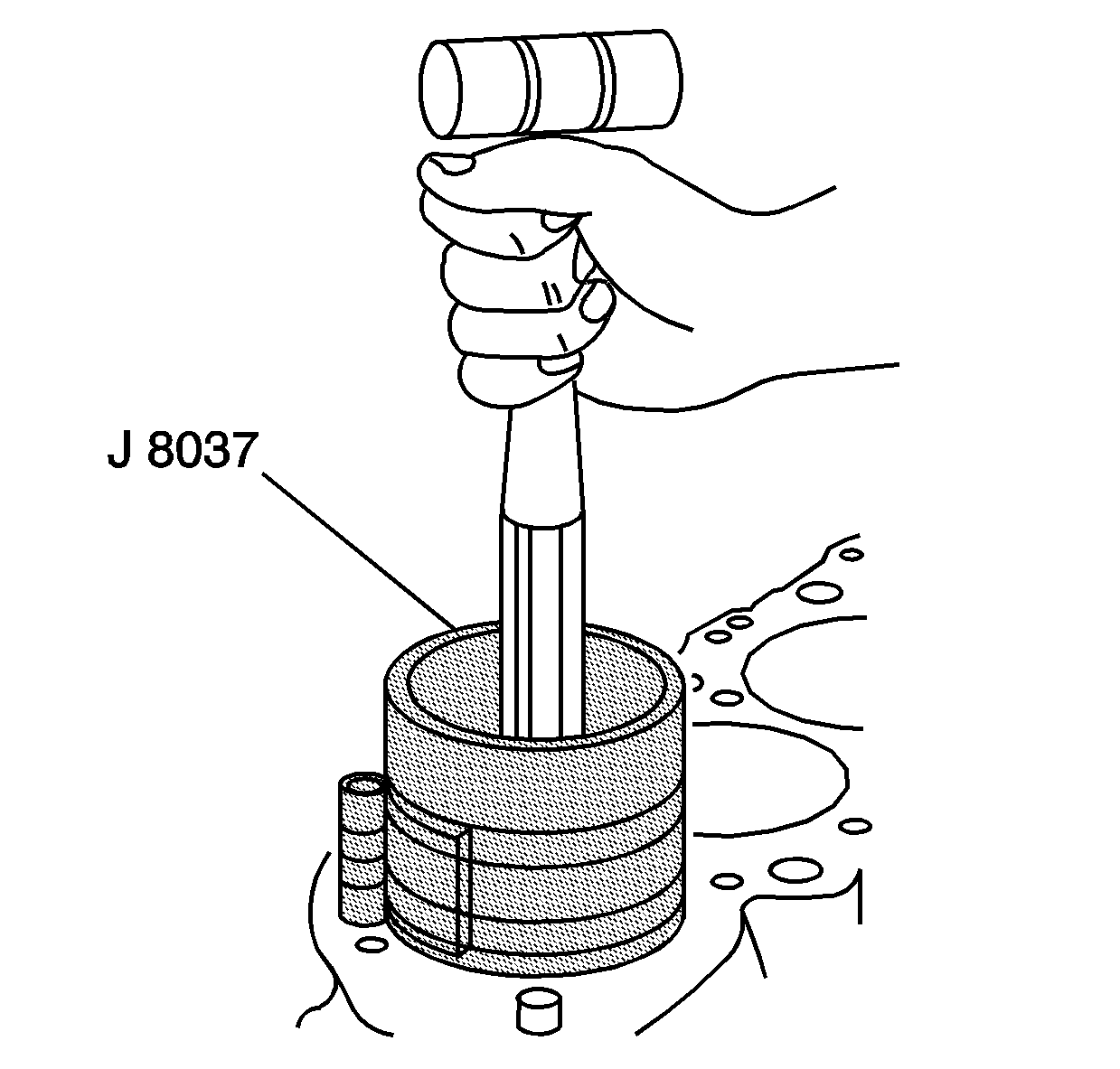
- Install the J 8037
onto the piston and compress the piston
rings.
- Use the J 8037
and
the J 5239
and lightly
tap the top of the piston with a wooden hammer handle.
- Hold the J 8037
firmly
against the engine block until all of the piston rings have entered the cylinder
bore.
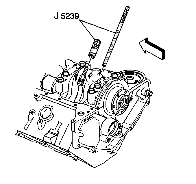
- Use the J 5239
in order to guide the connecting rod
onto the crankshaft journal.
- Remove the J 5239
.
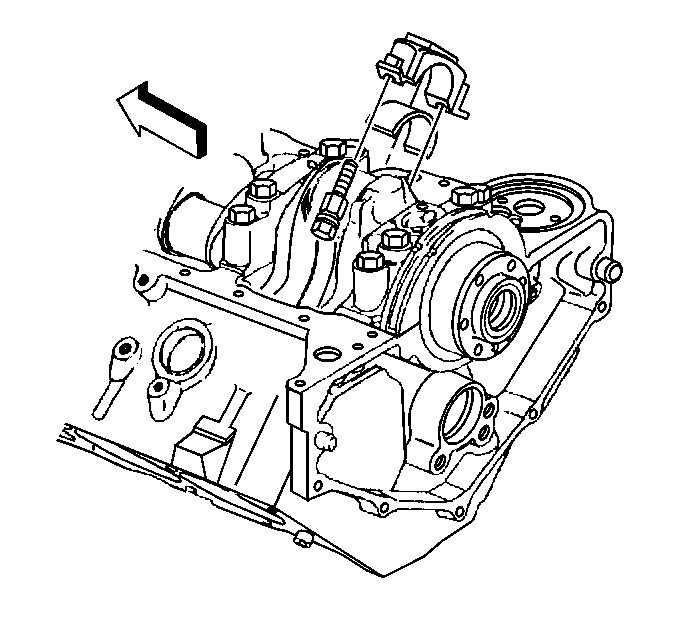
Notice: Do not shim, scrape, or file bearing inserts. Do not touch the bearing
surface of the insert with bare fingers. Skin oil and acids will etch the
bearing surface.
- Install the connecting rod cap and lower connecting rod bearing.
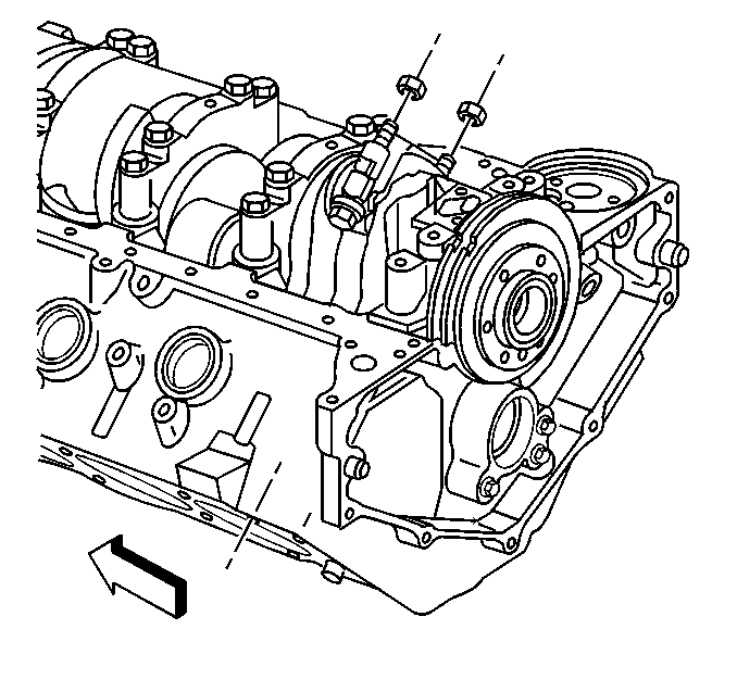
Notice: Use the correct fastener in the correct location. Replacement fasteners
must be the correct part number for that application. Fasteners requiring
replacement or fasteners requiring the use of thread locking compound or sealant
are identified in the service procedure. Do not use paints, lubricants, or
corrosion inhibitors on fasteners or fastener joint surfaces unless specified.
These coatings affect fastener torque and joint clamping force and may damage
the fastener. Use the correct tightening sequence and specifications when
installing fasteners in order to avoid damage to parts and systems.
- Install the connecting
rod nuts.
Tighten
Tighten the connecting rod nuts to 64 N·m (47 lb ft).
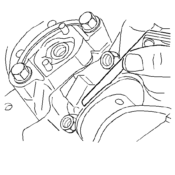
- Once the piston and connecting
rod assemblies have been installed, lightly tap each connecting rod assembly
(parallel to the crankpin) in order to make sure that they have side clearance.
- Use a feeler gauge or a dial indicator to measure the side clearance
between the connecting rod caps. The rod side clearance should be 0.033-0.584 mm
(0.0013-0.0230 in).


