For 1990-2009 cars only
- Remove the transmission fluid pressure manual valve position switch (TFP manual valve position switch) bolts (76) and the TFP valve position switch (40).
- Remove the control valve body assembly bolt (35) and the lube oil pipe retainer (37).
- Remove the lube oil pipe (39).
- Remove the control valve body assembly bolts (35).
- Remove the manual shaft detent spring assembly (41).
- Remove the control valve assembly (44) including the following:
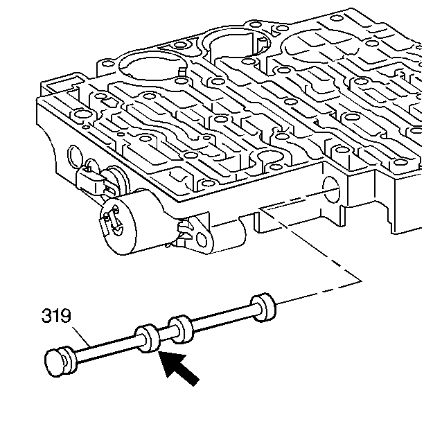
- Remove the manual valve (319) from the control valve assembly to prevent any damage.
- Inspect the manual valve (319) for nicks and burrs.
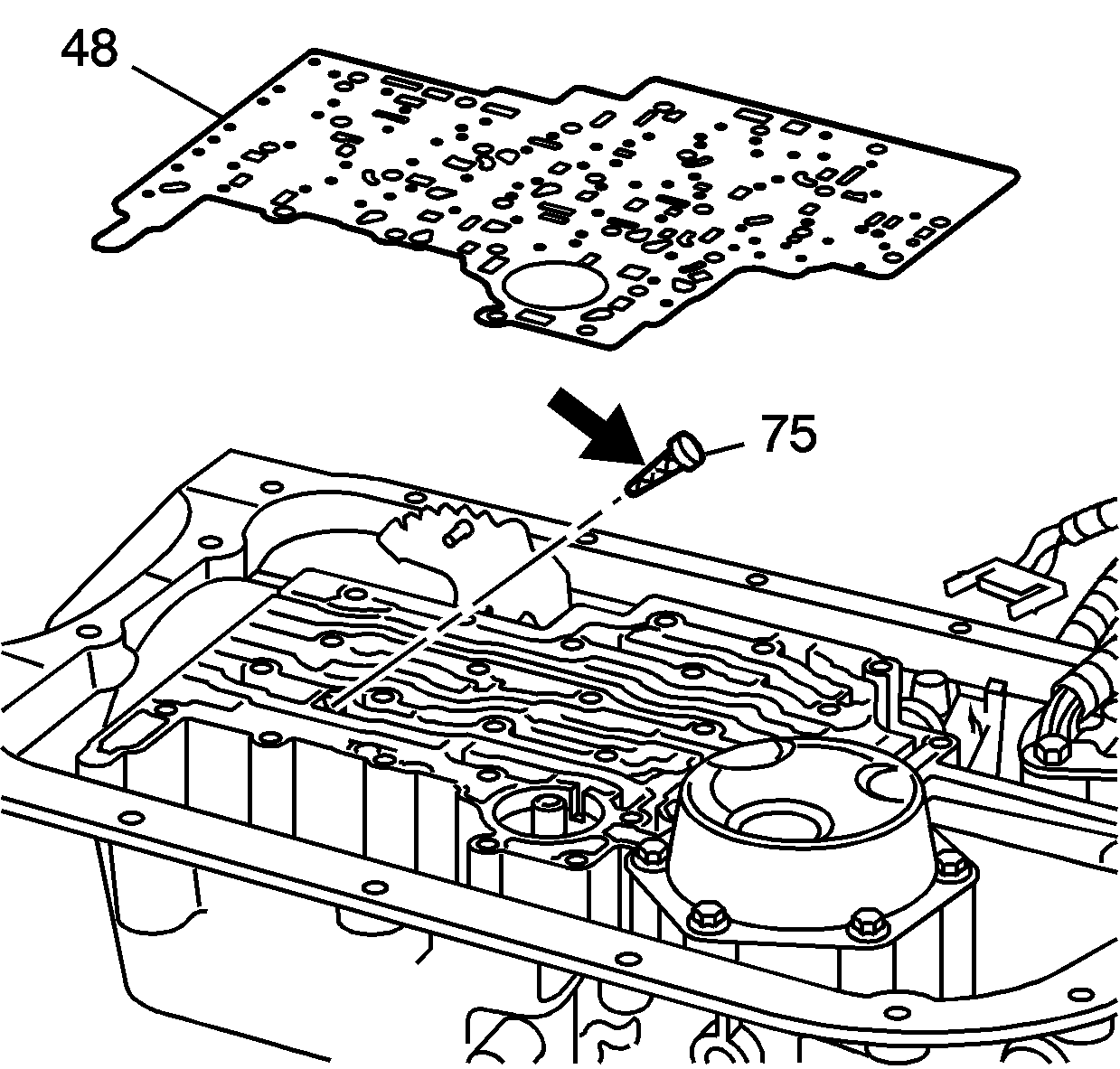
- Remove the spacer plate to case gasket (48) from the case. The gasket may stick to the spacer plate.
- Remove the PWM solenoid screen (75) from the case passages.
- Inspect the PWM solenoid screen (75) for debris and damage.
- Remove the eight checkballs (54) (nine checkballs for some models).
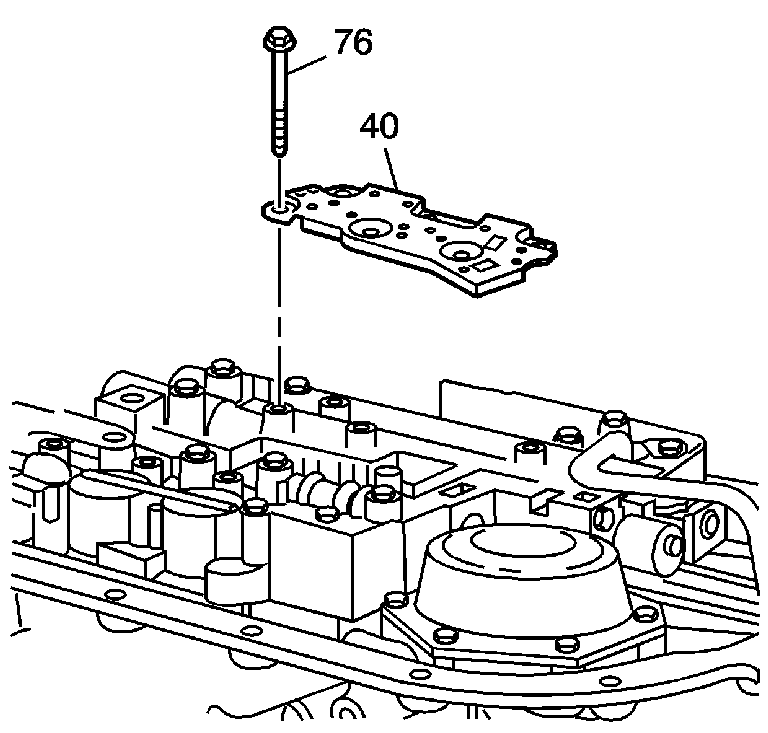
Important: The five O-rings should remain attached to the TFP manual valve position switch (40).
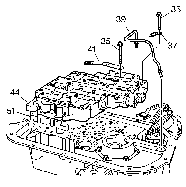
| • | The accumulator housing assembly (51) |
| • | The control valve body to spacer plate gasket |
| • | The control valve body spacer plate |
| • | The accumulator housing to spacer plate gasket |
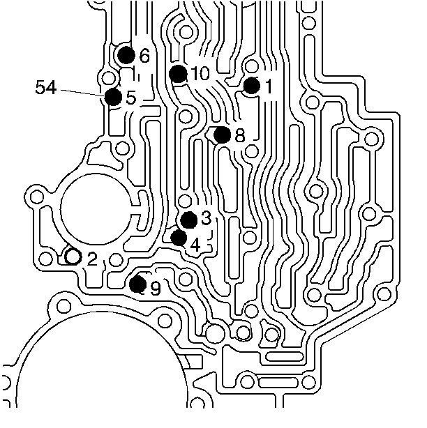
Important: Do not use a magnet in order to remove the checkballs. This may magnetize the checkballs, causing metal particles to stick to them.
