Tools Required
| • | J 26900-13 Magnetic Indicator Base |
| • | J 8001 Dial Indicator |
| • | J 41793 Master Differential Bearings |
- Install one new 0.689-0.838 mm (0.027-0.033 in) inboard shim onto each side of the differential case assembly.
- Install the J 41793 onto each side of the differential case assembly.
- Install the differential case assembly with the J 41793 into the axle housing.
- Install the bearing caps.
- Install the bearing cap bolts.
- Assemble the J 8001 and the J 26900-13 and install onto the ring gear side of the axle housing.
- Position the indicator of the J 8001 onto the flat surface of the differential case assembly.
- While pushing the differential case assembly towards the J 8001 , set the dial of the J 8001 to zero.
- Move the differential case assembly away from the J 8001 in order to obtain a reading on the J 8001 .
- Remove the bearing cap bolts.
- Remove the bearing caps.
- Remove the differential case assembly and the J 41793 from the axle housing.
- Remove the J 41793 from the differential case assembly.
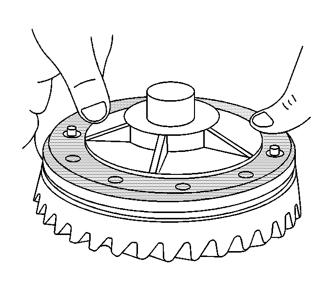
- Install the ring gear to the differential case assembly.
- Install the new ring gear bolts. Tighten the ring gear bolts alternately and in stages, gradually pulling the ring gear onto the differential case assembly.
- Install the J 41793 to the differential case assembly.
- Install the differential case assembly with the J 41793 into the axle housing.
- Install the bearing caps.
- Install the bearing cap bolts.
- Assemble the J 8001 and the J 26900-13 and install onto the axle housing.
- Position the indicator of the J 8001 onto to the flat surface of one of the ring gear bolts of the differential case assembly.
- While pressing the ring gear against the drive pinion, set the dial of the J 8001 to zero.
- Move the differential case assembly away from the pinion in order to obtain a reading on the J 8001 .
- In order to determine the amount of shim thickness needed for the right side of the differential case assembly-Measurement C, subtract the value obtained for the left, or ring gear, side of the differential case assembly-Measurement B, from the total shim pack size required determined-Measurement A.
- Remove the J 8001 and the J 26900-13 from the axle housing.
- Remove the J 41793 from the differential case assembly.
- Determine the differential side bearing preload. Refer to Differential Carrier Bearing Preload Adjustment .
Notice: If your axle assembly has selective outboard spacers and one 0.76 mm (0.030 inch) shim (each side) between the differential case and bearing cone. Make your measurements with the outboard spacers removed, but with the 0.76 mm (0.030 inch) shim assembled on the differential case trunion placed between the case and the master differential bearings. The selective outboard spacers are available in sizes (thickness) from 5.18 mm (0.2040 inch) to 6.10 mm (0.2400 inch), in 0.08 mm (0.003 inch) increments. The dial indicator should have the capability of making measurements up to 12.7 mm (0.500 inch).
Important: The ring gear must not be installed on the differential case assembly. If the ring gear is installed on the differential case assembly, it must be removed.
Important: Install the bearing caps into the same position from which each was removed.
Notice: Use the correct fastener in the correct location. Replacement fasteners must be the correct part number for that application. Fasteners requiring replacement or fasteners requiring the use of thread locking compound or sealant are identified in the service procedure. Do not use paints, lubricants, or corrosion inhibitors on fasteners or fastener joint surfaces unless specified. These coatings affect fastener torque and joint clamping force and may damage the fastener. Use the correct tightening sequence and specifications when installing fasteners in order to avoid damage to parts and systems.
Tighten
Tighten the bearing cap bolts finger tight. Do not torque the bolts
to specification at this time.
Repeat the step until a consistent reading is obtained.
Record the reading. Record the number of thousandths that the dial indicator traveled, not the reading on the dial. This value is the total amount of shim thickness needed for the differential case assembly-Measurement A.
Important: Do not remove the inboard shims from either side of the differential case assembly. If the shims must be removed, mark the shims accordingly so that they can be reassembled onto the correct side of the differential case assembly.

Important: The mating surface of the ring gear and the differential case assembly must be clean and free of burrs before installing the ring gear.
Align the holes in the differential case assembly and the holes in the ring gear.
Tighten
Tighten the ring gear bolts in sequence to 298 N·m (220 lb ft).
Important: Install the bearing caps into the same position from which each was removed.
Tighten
Tighten the bearing cap bolts finger tight. Do not torque the bolts
to specification at this time.
Repeat the step until a consistent reading is obtained.
Record the reading. Record the number of thousandths that the dial indicator traveled, not the reading on the dial. This value is the amount of shim thickness needed for the left, or ring gear, side of the differential case assembly-Measurement B.
This value is amount of shim thickness needed for the right side of the differential case assembly without setting the differential side bearing preload and the backlash.
Important: Do not remove the inboard shims from either side of the differential case assembly. If the shims must be removed, mark the shims accordingly so that they can be reassembled onto the correct side of the differential case assembly.
