Info - Automatic Engine Shutdown Feature

| Subject: | Automatic Engine Shutdown Feature |
| Models: | 1997-2001 Chevrolet and GMC F Model (T-Series) Medium Duty Tilt Cab Models |
| 1997-2001 Isuzu FSR/FTR/FVR Commercial Vehicles |
| with Air Brakes (RPO JE4) and Automatic Engine Shutdown (RPO KPJ) |
Some of the above listed vehicles may have an Automatic Engine Shutdown feature that does not function as advertised. If the vehicle is being driven with low oil pressure or high coolant temperature, the driver will be warned by a illuminated "Check Gauges" telltale light in the instrument cluster and by an audible tone. These portions of the feature operate as advertised. However, if the driver ignores these warnings and continues to drive the vehicle, the engine may not automatically shutdown and engine damage could occur.
Engineering has found that two wire circuits that were needed to connect the Multifunction Alarm Module (MFAM) to wiring inside the cab were missing. The missing MAFM feed signals precluded actuation of the automatic engine shutdown for low oil pressure and high coolant temperature.
Customers who purchased the suspect vehicles are being reimbursed the full purchase price of the option KPJ. If a customer chooses to have the Automatic Engine Shutdown feature enabled, rework the I/P wiring harness by adding two additional wires to provide the missing signal feeds to the MFAM. Use the procedure and part number listed below.
Harness Rework Procedure
- Obtain standard stock 18 gauge red wire and cut to a length of 3048 mm (120 in).
- Obtain standard stock 18 gauge green wire (or any color other than red) and cut to a length of 3048 mm (120 in).
- Remove the IP cluster trim plate.
- Remove the IP cluster.
- Remove the speedometer.
- Remove the radio and heater control trim panel.
- Remove the heater control.
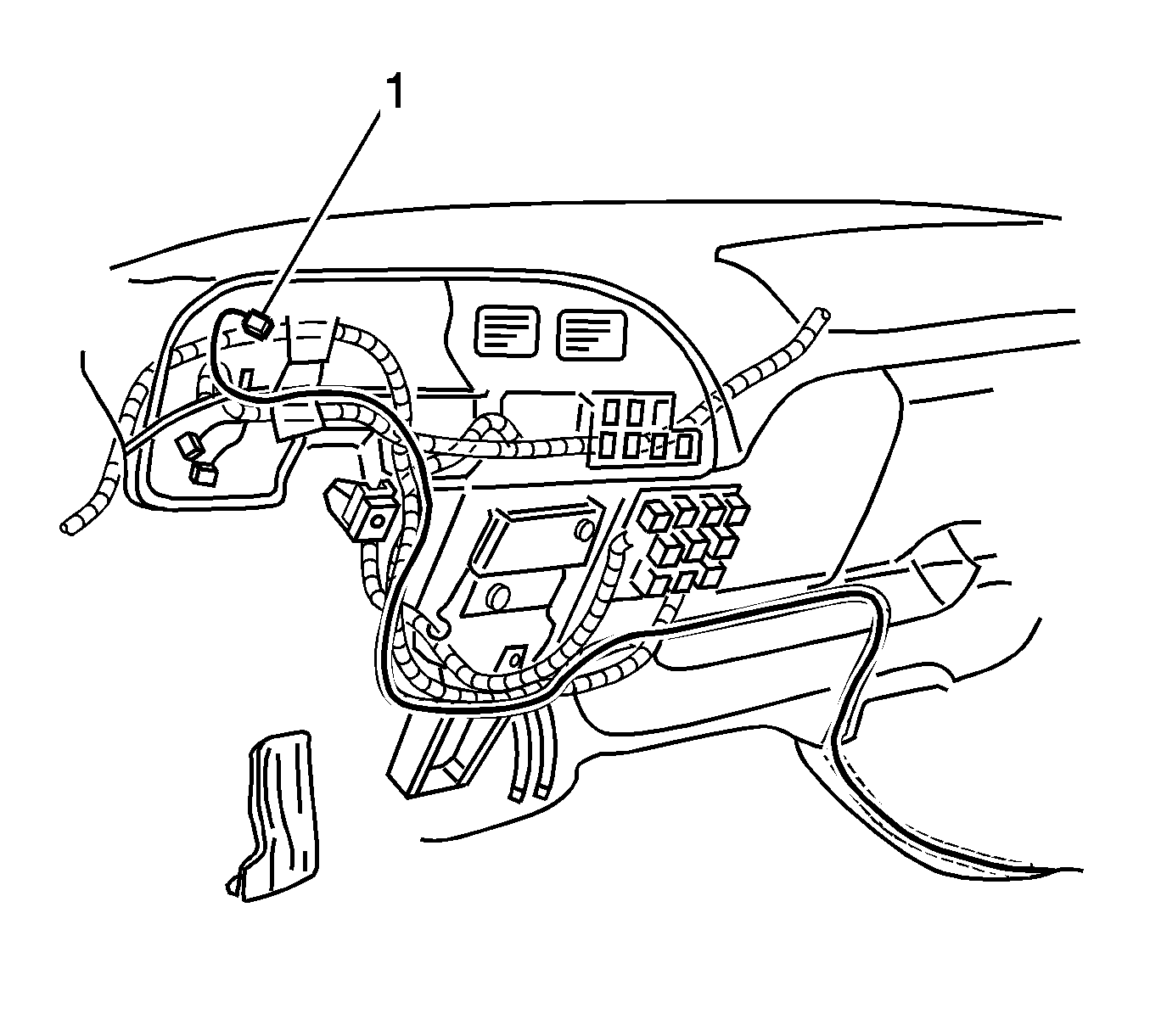
- Locate and pull out the hour meter connector (1) from the main IP harness.
- Strip 7.5 mm (5/16 in) of insulation from the yellow wire of the hour meter connector.
- Strip 7.5 mm (5/16 in) of insulation from one end of the red wire.
- Splice the new red wire to the yellow wire using the clip, P/N 01839906.
- Apply 60/40 rosin core solder to the opening in the back of the clip. Follow the manufacturer's instructions for solder equipment.
- Tape the entire splice area.
- Remove the steering column covers.
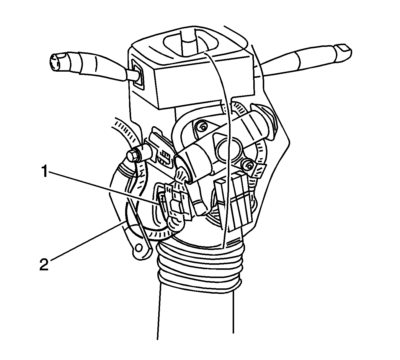
- Remove the clip (1) securing the ignition switch harness to the steering column.
- Remove the tape as needed.
- On the ignition switch harness (2), cut the plastic conduit back 10 mm (0.394 in) to expose the wires.
- Pass the new green wire through the conduit.
- Locate the yellow wire coming from the ignition switch.
- Strip 7.5 mm (5/16 in) of insulation from the yellow wire.
- Strip 7.5 mm (5/16 in) of insulation from one end of the green wire.
- Splice the new green wire to the yellow wire using the clip, P/N 01839906.
- Apply 60/40 rosin core solder to the opening in the back of the clip. Follow the manufacturer's instructions for solder equipment.
- Tape the entire splice and previously removed areas.
- Reinstall the clip securing the ignition switch harness to the steering column.
- Reinstall the steering column covers.
- Enclose the entire length of both red and green wires into the plastic conduit. Route along the existing IP harness as shown. Secure as needed using tie straps.
- Remove the passenger door sill plate.
- Lift up the passenger floor mat and route the new jumper harness along the floor and under the seat.
- Flip the passenger seat cushion forward.
- Strip 7.5 mm (5/16 in) of insulation from each end of both wires of the new jumper harness.
- Crimp the terminals, P/N 12146447, to each end of both wires.
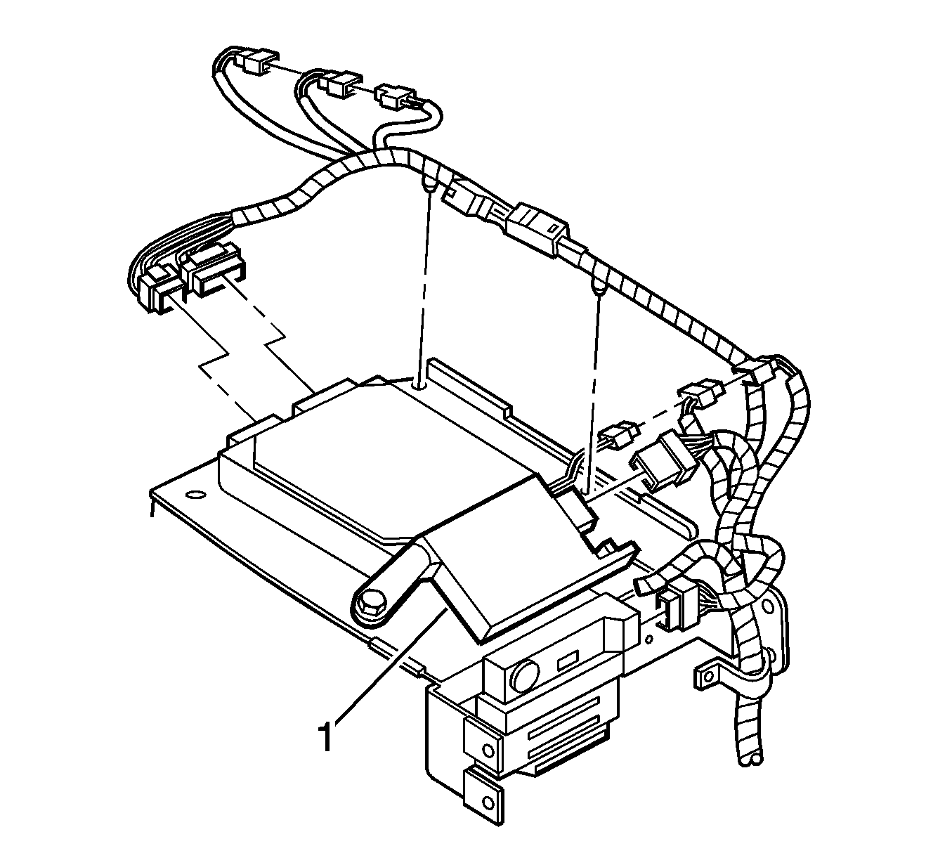
- Disconnect the multifunction alarm module (1) 16-way connector.
- Remove the TPA from the connector and install the terminal of the new red wire into cavity A2.
- Install the terminal of the new green wire into cavity A4.
- Reinstall the TPA, the connector and the seat cushion.
- Reinstall the passenger door sill plate.
- Reinstall the heater control.
- Reinstall the radio and heater control trim panel.
- Reinstall the speedometer.
- Reinstall the IP cluster.
- Reinstall the IP cluster trim plate.
- Verify proper operation of the Automatic Engine Shutdown feature by doing the following steps:


| • | Flip the passenger seat cushion forward. |
| • | Locate the gray wire from the pigtail connector of the multifunction alarm module. |
| • | Start the engine and ground out the gray wire in order to simulate a high coolant temperature condition. |
| • | If the feature is functioning properly, the Check Gauge lamp will illuminate, a continuous audible tone will sound and, after approximately 25 seconds, the engine will shut down. |
| • | If the engine does not shut down, then replace the multifunction alarm module. |
Parts Information
For Chevrolet and GMC Models:
Part Number | Description | Qty |
|---|---|---|
12146447 | Terminal | 2 |
01839906 | Splice Clip | 2 |
The terminals and splice clips are included in the Terminal Repair Kit J 38125-A and available from Kent-Moore (1-800-345-2233) or GMSPO.
For Isuzu Models:
Part Number | Description | Qty |
|---|---|---|
8-12146-447-0 | Terminal | 2 |
8-01839-906-0 | Splice Clip | 2 |
The terminals and splice clips are included in the Terminal Repair Kit J 38125-A and available from Kent-Moore (1-800-345-2233) or AIPDN.
Warranty Information
Please advise the customer that the labor and part cost for this harness rework will not be covered under the vehicle's warranty. All cost associated with this bulletin is the customer's responsibility. The following is a suggested repair guide only.
Labor Operation | Labor Time |
|---|---|
N/A | 1.1 hrs |
