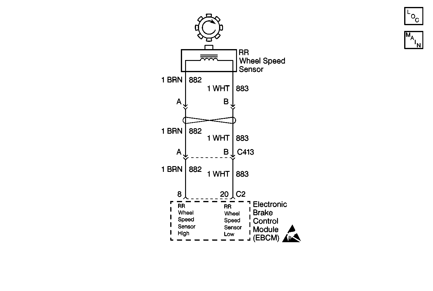
Circuit Description
The wheel speed sensor coil emits an electromagnetic field. A toothed ring on the wheel passes by the wheel speed sensor and disrupts this electromagnetic field. The disruption in the field causes the wheel speed sensor to produce a sinusoidal (AC) voltage signal. The frequency and amplitude of the sinusoidal (AC) voltage signal are proportional to the speed of the wheel. The amplitude of the wheel speed signal is also directly related to the distance between the wheel speed sensor coil and the toothed ring. This distance is referred to as the air gap.
Conditions for Setting the DTC
| • | No output from the right rear wheel speed sensor for 1.0 second. |
| • | Excessive right rear wheel speed sensor resistance for 1.0 second. |
Action Taken When the DTC Sets
| • | The ABS indicator lamp turns on |
| • | The ABS disables |
DTC C0231 is a Condition Latched DTC, which indicates that the above actions remain true only as long as the condition persists.
Conditions for Clearing the DTC
| • | Repair the conditions responsible for setting the DTC |
| • | Use the Scan Tool Clear DTCs function |
Diagnostic Aids
Any of the following conditions may cause an intermittent malfunction:
| • | A poor connection |
| • | Wire insulation that is rubbed through |
| • | A wire breaks inside the insulation |
Thoroughly check any circuitry that is suspected of causing the intermittent complaint for the following conditions:
| • | Backed out terminals |
| • | Improper mating |
| • | Broken locks |
| • | Improperly formed or damaged terminals |
| • | Poor terminal to wiring connections |
| • | Physical damage to the wiring harness |
If the customer says that the ABS indicator lamp is on only during humid conditions such as rain, snow, or vehicle wash, then thoroughly inspect all wheel speed sensor circuits for signs of water intrusion. Use the following procedure:
- Spray the suspected area with a 5% salt water solution (two teaspoons of salt to 12 oz. of water)
- Drive the vehicle above 24 km/h (15 mph) for at least 30 seconds
If the DTC returns, replace the suspected harness.
When inspecting a wheel speed sensor, inspect the sensor terminals and the harness connector for corrosion. If evidence of corrosion exists, replace the wheel speed sensor. Refer to Rear Wheel Speed Sensor Replacement .
Test Description
The numbers below refer to the steps in the diagnostic table:
-
This step checks the resistance of the right rear wheel speed sensor circuit.
-
This step checks the resistance of the right rear wheel speed sensor wiring.
-
This step checks resistance of the right rear wheel speed sensor.
Step | Action | Value(s) | Yes | No |
|---|---|---|---|---|
1 | Was the Diagnostic System Check performed? | -- | Go to Step 2 | Go to Diagnostic System Check |
Is the resistance measurement within the specified range? | 1500-2500 ohms | Go to Step 5 | Go to Step 3 | |
Is the resistance measurement within the specified range? | 0-2 ohms | Go to Step 4 | Go to Step 7 | |
Using a J 39200 , measure the resistance between terminal A and terminal B of the right rear wheel speed sensor pigtail. . Is the resistance measurement within the specified range? | 1500-2500 ohms | Go to Step 5 | Go to Step 8 | |
5 |
Does DTC C0231 set as a current DTC? | -- | Go to Step 6 | Go to Diagnostic Aids |
6 | Replace the EBCM. Refer to Electronic Brake Control Module Replacement . Is the repair complete? | -- | Go to Diagnostic System Check | -- |
7 | Repair the open or the high resistance in CKT 882 or CKT 883. Refer to Wiring Repairs in Wiring Systems. Is the repair complete? | -- | Go to Diagnostic System Check | -- |
8 | Replace the wheel speed sensor. Refer to Rear Wheel Speed Sensor Replacement . Is the repair complete? | -- | Go to Diagnostic System Check | -- |
