Inflatable Restraint Arming Sensor 2WD
Removal Procedure
Caution: Be very careful when handling the sensors during service procedures. Never strike the sensors. Never jar the sensors. These actions could result in personal injury, or improper operation of the Supplemental Inflatable Restraint (SIR) system. Carefully tighten all of the sensors, and all of the mounting bracket bolts to ensure proper operation. Never power up the SIR system when any one of the sensors is not rigidly attached to the vehicle. An unattached sensor could be easily activated causing the deployment of the air bag.
- Disable the SIR system. Refer to Disabling the SIR System
- Raise the vehicle. Refer to General Information in Section 0A.
- Disconnect the Connector Position Assurance (CPA) lock from the retainer.
- Disconnect the electrical connector.
- Remove the mounting bolts.
- Remove the sensor from the vehicle.
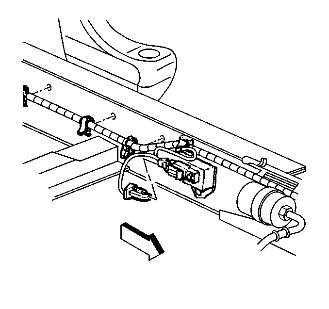
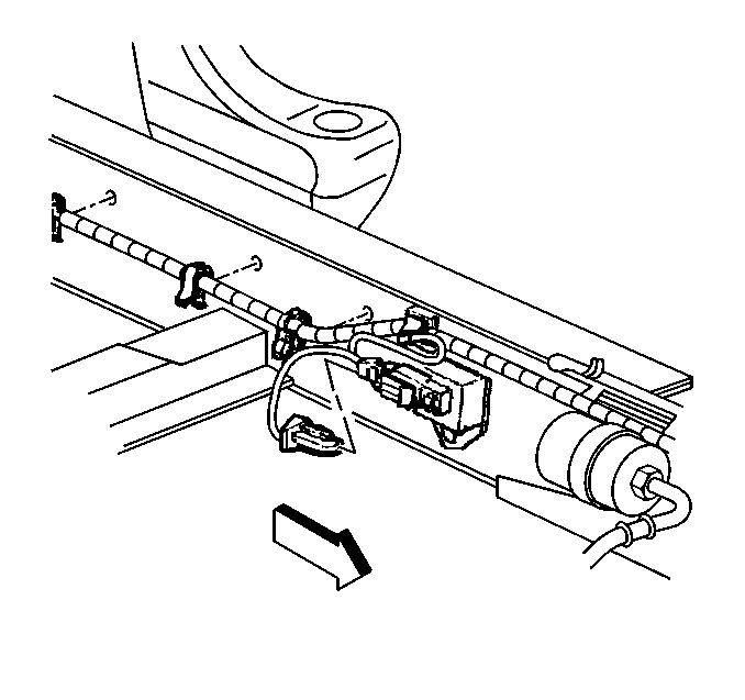
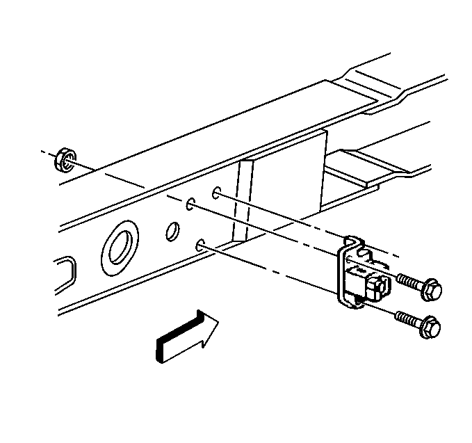
Important: Use the following repair procedures when the sensor mounting holes or fasteners are so badly damaged that the sensor may no longer be properly mounted.
First Repair
- Remove the stripped fastener.
- Discard the stripped fastener.
- Enlarge the mounting hole in the sensor to 9 mm (0.350 in).
- Attach the sensor with the screw GM P/N 11515210 and the flanged hex nut GM P/N 15672934.
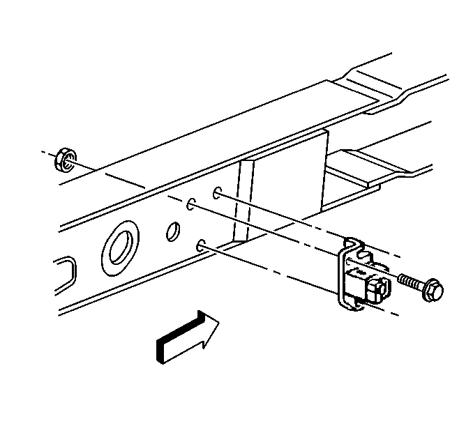
Tighten
Tighten the screw to 15 N·m (11 lb ft).
Refer to Fastener Notice in General Information.
Second Repair
- Remove the stripped fastener.
- Discard the stripped fastener.
- Enlarge the 9 mm mounting hole in the sensor to 11 mm (0.433 in).
- Enlarge the hole in the frame rail or cross-member to 9 mm (0.350 in).
- Use the screw GM P/N 11515215 to attach the sensor.

Tighten
Tighten the screws to 15 N·m (11 lb ft).
Refer to Fastener Notice in General Information.
Installation Procedure
- Install the sensor to the vehicle.
- Install the sensor mounting bolts.
- Connect the inflatable restraint arming sensor electrical connector.
- Install the Connector Position Assurance (CPA) lock to the retainer.
- Remove the safety stands.
- Lower the vehicle.
- Enable the SIR system. Refer to Enabling the SIR System

Tighten
Tighten the mounting bolts to 15 N·m (11 lb ft).
Refer to Fastener Notice in General Information.


Inflatable Restraint Arming Sensor 4WD
Removal Procedure
Caution: Be very careful when handling the sensors during service procedures. Never strike the sensors. Never jar the sensors. These actions could result in personal injury, or improper operation of the Supplemental Inflatable Restraint (SIR) system. Carefully tighten all of the sensors, and all of the mounting bracket bolts to ensure proper operation. Never power up the SIR system when any one of the sensors is not rigidly attached to the vehicle. An unattached sensor could be easily activated causing the deployment of the air bag.
- Disable the SIR system. Refer to Disabling the SIR System .
- Raise the vehicle. Refer to General Information in Section 0A.
- Disconnect the Connector Position Assurance (CPA) lock from the retainer.
- Disconnect the electrical connector.
- Remove the mounting bolts.
- Remove the sensor from the vehicle.
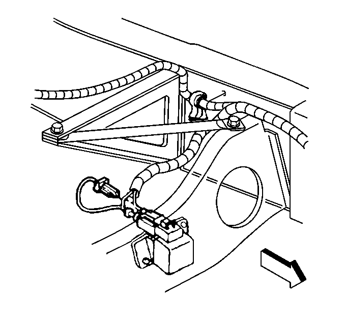
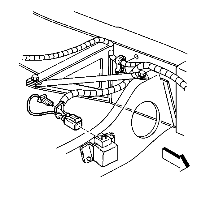
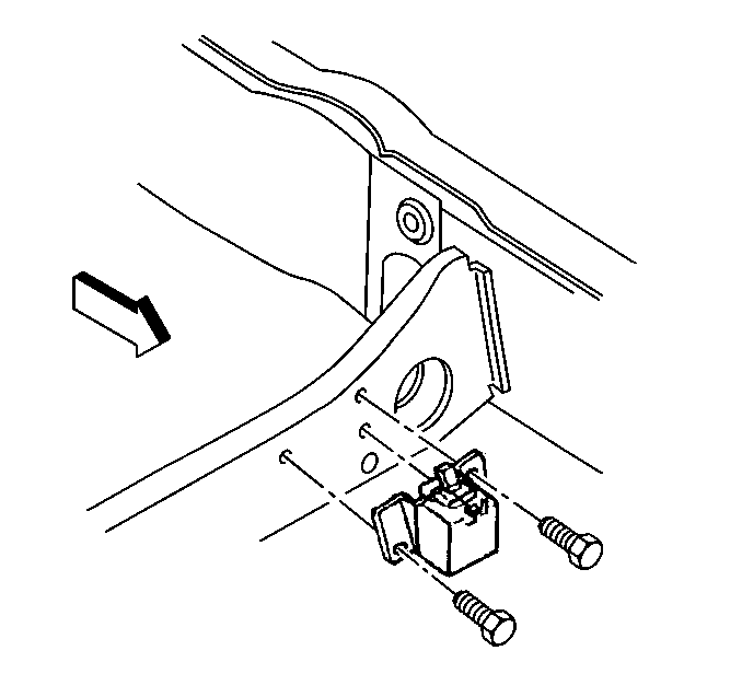
Important: Use the following repair procedures when the sensor mounting holes or fasteners are so badly damaged that the sensor may no longer be properly mounted.
First Repair
- Remove the stripped fastener.
- Discard the stripped fastener.
- Enlarge the mounting hole in the sensor to 9 mm (0.350 in).
- Attach the sensor with the screw GM P/N 11515210 and the flanged hex nut GM P/N 15672934.
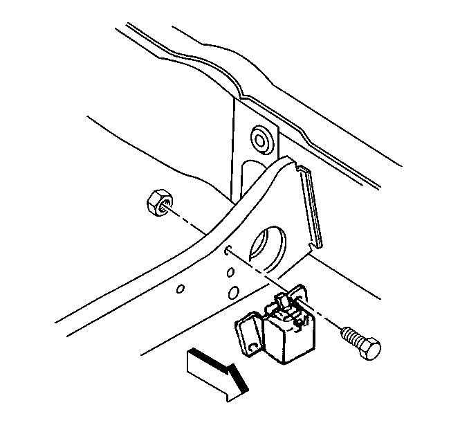
Tighten
Tighten the screw to 15 N·m (11 lb ft).
Refer to Fastener Notice in General Information.
Second Repair
- Remove the stripped fastener.
- Discard the stripped fastener.
- Enlarge the 9 mm (0.350 in) mounting hole in the sensor to 11 mm (0.433 in).
- Enlarge the hole in the frame rail or cross-member to 9 mm (0.350 in).
- Use the screw GM P/N 11515215 to attach the sensor.

Tighten
Tighten the screws to 15 N·m (11 lb ft).
Installation Procedure
- Install the sensor to the vehicle.
- Install the sensor mounting bolts.
- Connect the inflatable restraint arming sensor electrical connector.
- Install the Connector Position Assurance (CPA) lock to the retainer.
- Remove the safety stands.
- Lower the vehicle.
- Enable the SIR system. Refer to Enabling the SIR System .

Tighten
Tighten the mounting bolts to 15 N·m (11 lb ft).
Refer to Fastener Notice in General Information.


