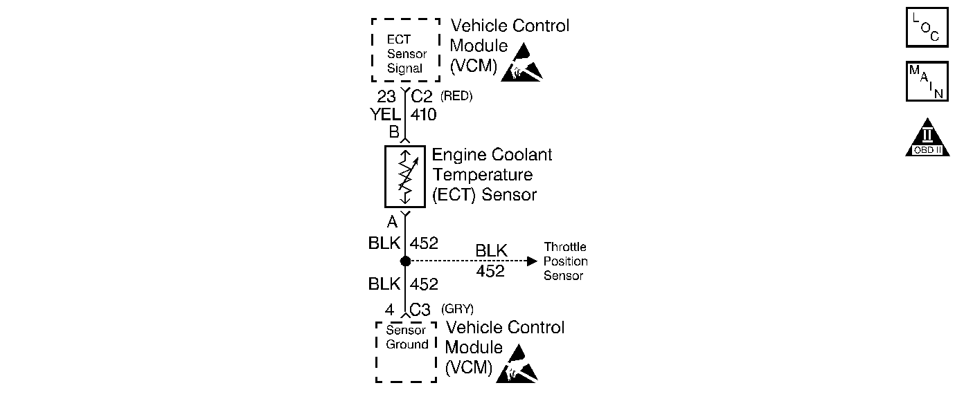
Circuit Description
The Engine Coolant Temperature (ECT) sensor is a thermistor which controls the signal voltage to the VCM. The VCM applies a voltage on a 5 volt reference circuit to the sensor. When the engine coolant is cold, the sensor's internal resistance is high resulting in a high voltage ECT Sensor Signal. As the engine coolant temperature increases, the sensor's internal resistance and ECT Sensor Signal decrease. This DTC is a type A DTC.
Conditions for Setting the DTC
| • | The engine run time is greater than 5 seconds |
| • | ECT signal voltage is less than 0.25 V |
Action Taken When the DTC Sets
The VCM turns the MIL ON when P0117 is reported and 1 failure has occurred.
Conditions for Clearing the MIL or DTC
| • | The control module turns OFF the MIL after 3 consecutive drive trips when the test has run and passed. |
| • | A history DTC will clear if no fault conditions have been detected for 40 warm-up cycles. A warm-up cycle occurs when the coolant temperature has risen 22°C (40°F) from the startup coolant temperature and the engine coolant reaches a temperature that is more than 70°C (158°F) during the same ignition cycle. |
| • | Use a scan tool in order to clear the DTCs. |
Diagnostic Aids
After starting the engine, the temperature should rise steadily to about 90°C (194°F) then stabilize when the thermostat opens.
Check for an intermittent short to ground in the ECT sensor signal circuit by moving the VCM harness at various locations and monitoring the ECT voltage on the scan tool. If the voltage varies, look for a short to ground in the area of the harness that caused the variance.
Use the Temperature vs. Resistance Value Table to test the coolant sensor at various temperature levels in order to evaluate the possibility of a skewed (mis-scaled) sensor. A skewed sensor could result in poor driveability concerns. Refer to Temperature vs Resistance .
Test Description
The numbers below refer to the step numbers on the diagnostic table.
-
If the fault is still present, the engine coolant voltage will measure less than 0.25 volts.
-
This test simulates a DTC P0118. If the VCM recognizes the high signal voltage and the scan tool display reads 40 volts or more, the VCM and the wiring are okay.
Step | Action | Value(s) | Yes | No |
|---|---|---|---|---|
1 |
Important: Before clearing the DTCs, use the scan tool in order to record the Freeze Frame and the Failure Records for reference. This data will be lost when the Clear DTC Information function is used. Was the Powertrain On-Board Diagnostic (OBD) System Check performed? | -- | ||
Does the scan tool display an ECT sensor voltage less than the specified value? | 0.25 V | |||
Does the scan tool display an ECT sensor voltage greater than the specified value? | 4.0 V | |||
4 |
Is the resistance at the specified value? | ∞ | ||
5 | The DTC is intermittent. Are any additional DTCs stored? | -- | Go to The Applicable DTC Table | Go to Diagnostic Aids |
6 | Repair the short to the ground in the ECT signal circuit. Refer to Wiring Repairs in Engine Electrical. Is the action complete? | -- | -- | |
7 | Replace the ECT sensor. Refer to Engine Coolant Temperature (ECT) Sensor Replacement . Is the action complete? | -- | -- | |
8 | Replace the VCM. Important: When replacing the VCM, the new VCM will need to be programmed. Refer to VCM Replacement/Programming . Is the action complete? | -- | -- | |
9 |
Does the scan tool indicate that this diagnostic ran and passed? | -- | ||
10 | Use the scan tool in order to displaythe Capture Info and Review Capture Info function. Are there any DTCs displayed that have not been diagnosed? | -- | Go to The Applicable DTC Table | System OK |
