| Table 1: | Air Temperature Valve Sensor and Motor |
| Table 2: | Blower Motor |
| Table 3: | Heater and A/C Control Module (Electronic Climate Control (EEC) Module) |
| Table 4: | Inside Air Temperature Sensor |
| Table 5: | HVAC Solenoid Assembly |
| Table 6: | Lower Discharge Air Temperature Sensor |
| Table 7: | Outside Ambient Temperature Sensor |
| Table 8: | Sun Load Temperature Sensor |
| Table 9: | Upper Discharge Air Temperature Sensor |
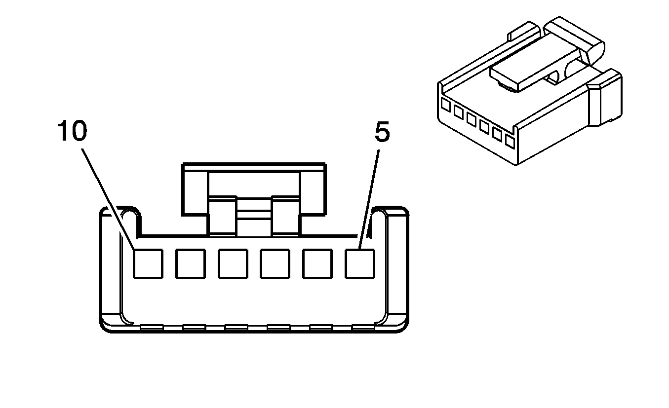
| |||||||
|---|---|---|---|---|---|---|---|
Connector Part Information |
| ||||||
Pin | Wire Color | Circuit No. | Function | ||||
5 | BRN | 341 | Fuse Output - Ignition | ||||
6 | DK BLU | 1199 | Air Temperature Valve Motor Feed | ||||
7 | YEL | 1791 | Air Temperature Valve Motor Return | ||||
9 | LT BLU | 733 | Air Temperature Valve Position Sensor Signal | ||||
10 | LT BLU/BLK | 1688 | Reference Voltage Feed - 5 Volt Reference | ||||
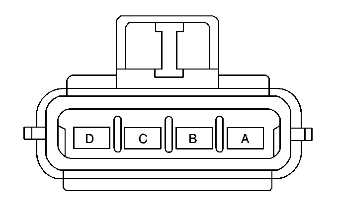
| |||||||
|---|---|---|---|---|---|---|---|
Connector Part Information |
| ||||||
Pin | Wire Color | Circuit No. | Function | ||||
A | BLK | 850 | Ground | ||||
B | ORN | 540 | Fuse Output-Battey-Type III Fuse | ||||
C | 760 | PPL/WHT | Blower Speed Signal-Speed Control-Low Energy | ||||
D | -- | -- | Not Used | ||||
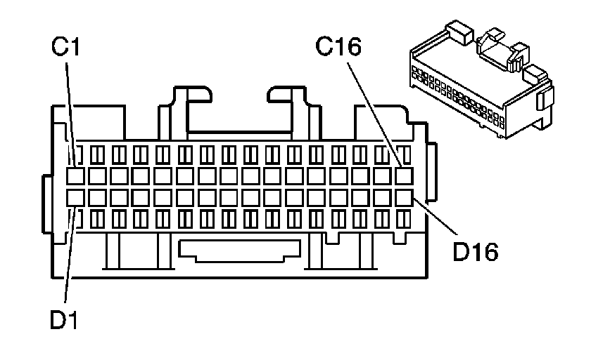
| ||||||||||
|---|---|---|---|---|---|---|---|---|---|---|
Connector Part Information |
| |||||||||
Pin | Wire Color | Circuit No. | Function | Component Connector Cavity | DTC(s) Affected | Possible Symptoms From a Faulty Circuit | ||||
C1 | LT BLU/BLK | 590 | Solar Sensor Input | Solar Sensor Terminal A | B0185 B0186 | Degraded Temperature Control During High Sun Load | ||||
C2 | BRN | 404 | Output Air Temperature (Upper) Input | Output Air Temperature (Upper) Terminal A | B0175 B0176 | Failure Will Force Temp to Cold (Loss of Temp Control) | ||||
C3 | LT GRN | 405 | Output Air Temperature (Lower) Input | Output Air Temperature (Lower) Terminal A | B0180 B0181 | May Force Temp Hot or Cold (Degraded Temp Control) | ||||
C4 | LT BLU | 733 | Elect Actuator ASM Position Feedback | Elect Actuator ASM Terminal 9 | B0408 B0415 B0416 | Degraded Temp Control | ||||
C5 | -- | -- | Not Used | -- | -- | -- | ||||
C6 | BRN | 341 | IGN 3 Input (Hot in RUN Only) | IP Fuse Block Terminal G1 | -- | -- | ||||
C7 | GRY | 1220 | Dimming Input for Illumination | SP205 | -- | -- | ||||
C8 | -- | -- | Not Used | -- | -- | -- | ||||
C9 | DK BLU | 1199 | Elect Actuator ASM Position Direction Control | Elect Actuator ASM Terminal 6 | B0409 | Degraded Temp Control | ||||
C10 | BLK | 1050 | Module Ground | SP204 Terminal K | -- | System Inoperative | ||||
C11 | WHT | 1038 | Class 2 | SP201 Terminal L | -- | Degraded Temp Control (Especially During Vehicle Warm-Up) | ||||
C12 | ORN | 340 | Battery Input (Hot at All Times) | IP Fuse Block Terminal C1 | -- | System Inoperative | ||||
C13 | LT BLU | 706 | Air Inlet Solenoid 5 (Low Side Driver) | Heater and A/C Solenoid Assembly Terminal 5 | -- | Degraded Mode Actuator Control | ||||
C14 | TAN | 363 | Air Inlet Solenoid 3 (Low Side Driver) | Heater and A/C Solenoid Assembly Terminal 3 | -- | Degraded Mode Actuator Control | ||||
C15 | PPL | 361 | Air Inlet Solenoid 1 (Low Side Driver) | Heater and A/C Solenoid Assembly | -- | Degraded Mode Actuator Control (Defrost Performance) | ||||
C16 | PPL/WHT | 760 | Blower Control Module ASM Speed Output | Blower Control Module ASM Terminal C | -- | Loss of Blower Motor Control | ||||
D1 | DK GRN | 734 | Inside Air Temperature Sensor Input | Inside Air Temperature Sensor Terminal A | B0165 B0166 | Degraded Temp Control | ||||
D2 | DK GRN/WHT | 636 | Ambient Air Temperature Sensor Input | Ambient Air Temperature Sensor Terminal B | B0160 B0161 | Degraded Temp Control | ||||
D3-D4 | -- | -- | Not Used | -- | -- | -- | ||||
D5 | LT BLU/BLK | 1688 | 5 Volt Reference | Electric Actuator ASM Terminal 10 | B0408 | Degraded Temp Control | ||||
D6-D7 | -- | -- | Not Used | -- | -- | -- | ||||
D8 | LT BLU | 203 | A/C Compressor Request (VCM) | A/C Compressor Switch Terminal A | -- | Loss of A/C | ||||
D9 | BLK | 552 | Sensor Ground | S280 | -- | Many DTCs Will Set Degraded Temp Control | ||||
D10 | YEL | 1791 | Electric Actuator ASM Ground | Electric Actuator ASM Terminal 7 | B0408 | Decreased Temp Control | ||||
D11-D13 | -- | -- | Not Used | -- | -- | -- | ||||
D14 | WHT | 193 | Rear Defogger Relay (Low Side Driver) | underhood fuse block C1 Terminal F8 | -- | Loss of Rear Defogger Control | ||||
D15 | LT GRN/BLK | 366 | Air Inlet Solenoid 4 (Low Side Driver) | Heater and A/C Solenoid Assembly Terminal 5 | -- | Degraded Mode Actuator Control | ||||
D16 | RED | 362 | Air Inlet Solenoid 2 (Low Side Driver) | Heater and A/C Solenoid Assembly Terminal 2 | -- | Degraded Mode Actuator Control | ||||
NOTE: Refer to Typical Scan Tool Data Values for more information. | ||||||||||
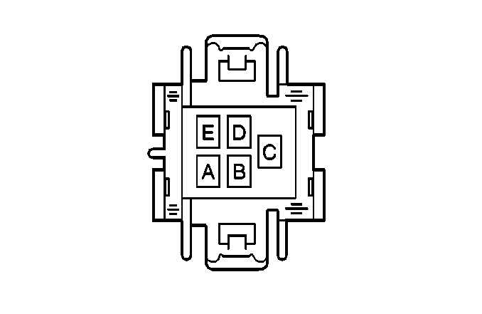
| |||||||
|---|---|---|---|---|---|---|---|
Connector Part Information |
| ||||||
Pin | Wire Color | Circuit No. | Function | ||||
A | ORN | 52 | Blower Switch Output - High | ||||
B | LT BLU | 72 | Blower Switch Output - Medium 2 | ||||
C | TAN | 63 | Blower Switch Output - Medium 1 | ||||
D | -- | -- | Not Used | ||||
E | BRN | 64 | High Speed Blower Relay Feed - Coil | ||||
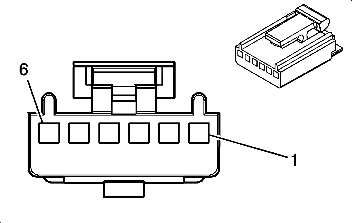
| |||||||
|---|---|---|---|---|---|---|---|
Connector Part Information |
| ||||||
Pin | Wire Color | Circuit No. | Function | ||||
1 | PPL | 361 | Mode Valve Solenoid Output - Defrost | ||||
2 | RED | 362 | Mode Valve Solenoid Output - Panel Vents | ||||
3 | TAN | 363 | Mode Valve Solenoid Output - Upper | ||||
4 | LT GRN/BLK | 366 | Mode Valve Solenoid Output - Lower | ||||
5 | LT BLU | 706 | Mode Valve Solenoid Output - Recirculation | ||||
6 | BRN | 341 | Fuse Output - Ignition 3 - Type III Fuse | ||||
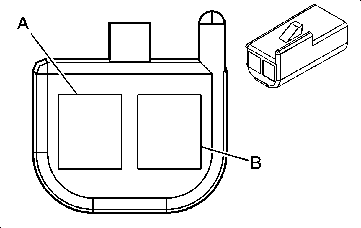
| |||||||
|---|---|---|---|---|---|---|---|
Connector Part Information |
| ||||||
Pin | Wire Color | Circuit No. | Function | ||||
A | LT GRN | 405 | Fuse Output - Battery | ||||
B | BLK | 552 | Sensor Return | ||||
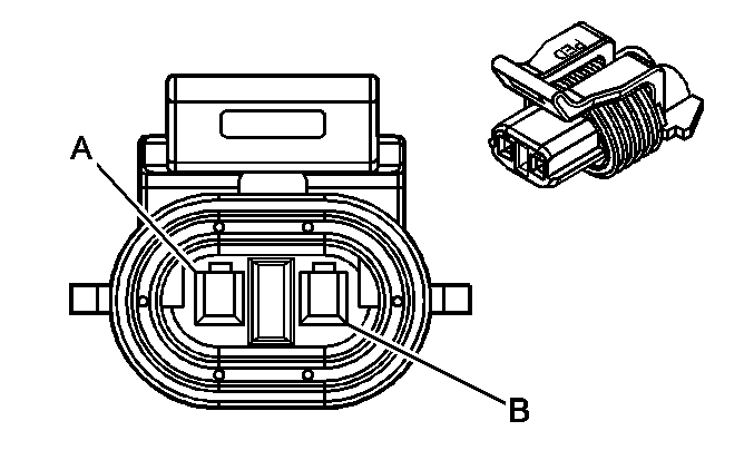
| |||||||
|---|---|---|---|---|---|---|---|
Connector Part Information |
| ||||||
Pin | Wire Color | Circuit No. | Function | ||||
A | BLK | 552 | Sensor Return | ||||
B | DK GRN/WHT | 636 | Outside Ambient Temperature Sensor Signal | ||||

| |||||||
|---|---|---|---|---|---|---|---|
Connector Part Information |
| ||||||
Pin | Wire Color | Circuit No. | Function | ||||
A | LT BLU/BLK | 590 | Solar Sensor Signal - Drive | ||||
B | BLK | 552 | Sensor Return | ||||

| |||||||
|---|---|---|---|---|---|---|---|
Connector Part Information |
| ||||||
Pin | Wire Color | Circuit No. | Function | ||||
A | BRN | 404 | Fuse Output - Battery | ||||
B | BLK | 552 | Sensor Return | ||||
