Removal Procedure
- Unlock the steering column so that the steering linkage is free to move.
- Raise and support the vehicle. Refer to Lifting and Jacking the Vehicle in General Information.
- Remove the front tires and wheels. Refer to Wheel Removal in Tires and Wheels.
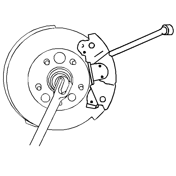
- In order to prevent the drive axle from turning, insert a drift through the brake caliper and into one of the rotor vanes.
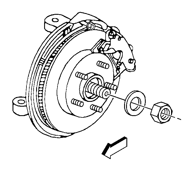
- Remove the wheel drive shaft nut and washer.
- Remove the drift from the brake rotor.
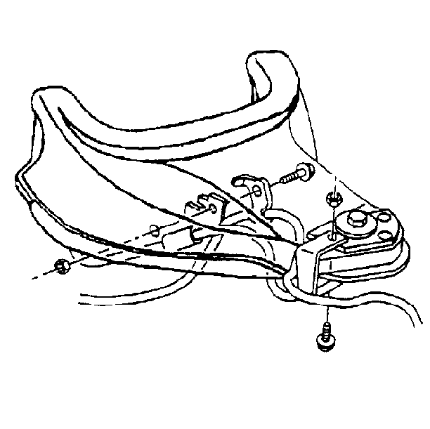
- Remove the nut and the bolt from the upper control arm holding both the ABS wire and the brake hose support brackets.
- Remove the nut and the bolt from the upper control arm ball joint holding the ABS wire support bracket.
- Strap the frame to the hoist in order to prohibit movement.
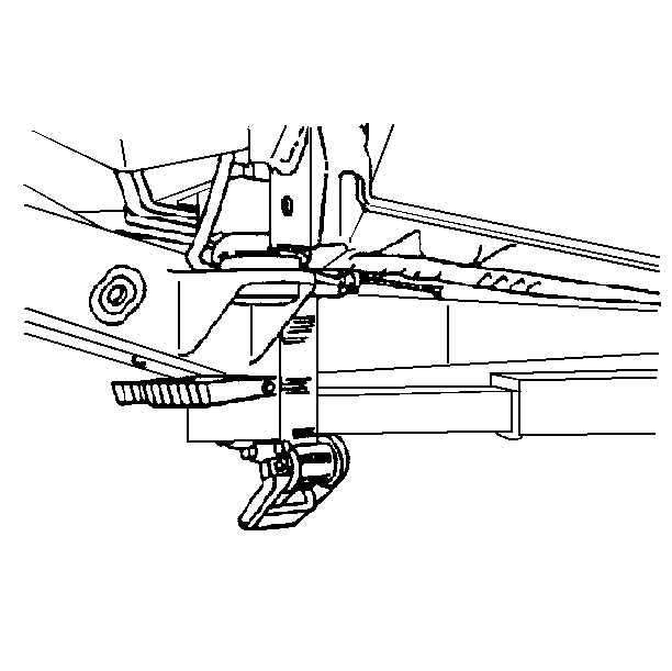
- Position a safety stand under the lower control arm.
- Support the weight of the steering knuckle assembly and lower control arm with a safety stand.
- Disengage the wheel drive shaft from the hub by placing a brass drift against the outer end of the wheel drive shaft. Sharply strike the brass drift with a hammer. The nut can be partially re-installed to protect the threads.
- Remove the shock absorber from the lower mount only. Refer to Shock Absorber Replacement in Front Suspension.
- Separate the upper ball joint from the steering knuckle. Refer to Upper Control Arm Ball Joint Replacement in Front Suspension.
- Asperity the lower ball joint from the steering knuckle. Refer to Lower Control Arm Ball Joint Replacement in Front Suspension.
- Remove the steering knuckle and brake assembly from the wheel drive shaft.
- Support the steering knuckle and brake assembly with a piece of wire in order to prevent damage to the outer tie rod, ABS wire, and brake hose.
- Lower the safety stand from the lower control arm to relieve the pressure of the torsion bar and to allow for clearance.
- Remove the front differential carrier shield.
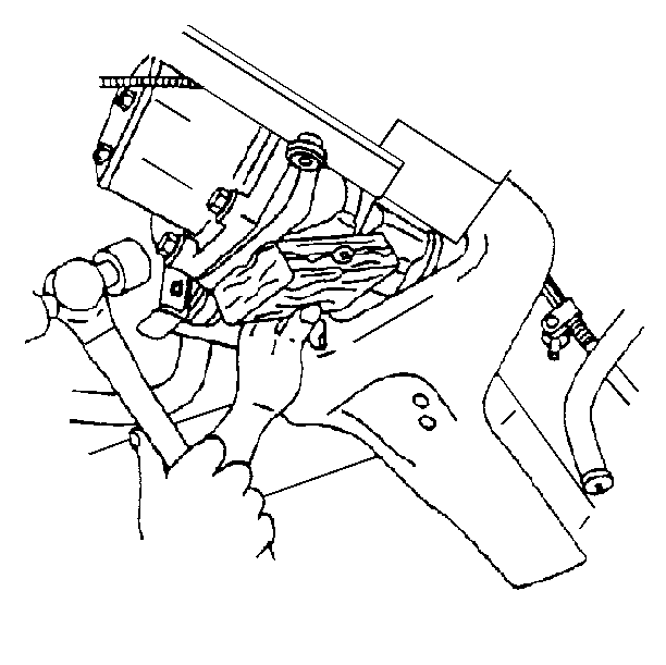
- Disconnect the left side wheel drive shaft from the differential carrier by placing a block of wood or a brass drift against the tripot housing. Firmly strike the block of wood outward from the case with a hammer. Strike hard enough to overcome the snap ring pressure holding the shaft in.
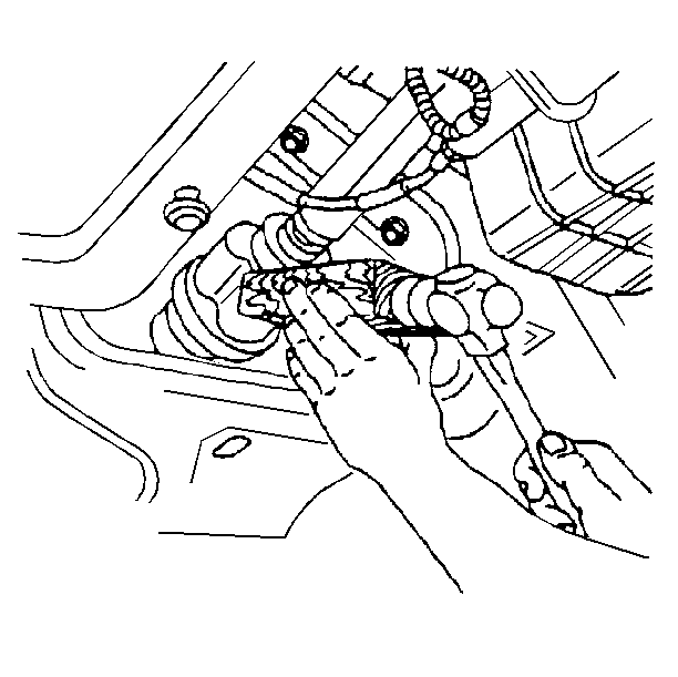
- Disconnect the right side wheel drive shaft from the differential carrier by placing a block of wood or a brass drift against the tripot housing. Firmly strike the block of wood outward from the case with a hammer. Strike hard enough to overcome the snap ring pressure holding the shaft in.
- Pull the wheel drive shaft straight out from the differential carrier.
- Support the wheel drive shaft so as not to tear the boot.
- Remove the wheel drive shaft.
Caution: To prevent personal injury and/or component damage, do not allow the weight of the vehicle to load the front wheels, or attempt to operate the vehicle, when the wheel drive shaft(s) or wheel drive shaft nut(s) are removed. To do so may cause the inner bearing race to separate, resulting in damage to brake and suspension components and loss of vehicle control.
Notice: Be careful that the safety stand does not damage or bend any components it may contact.
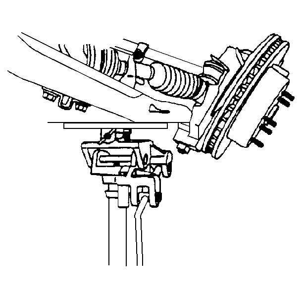
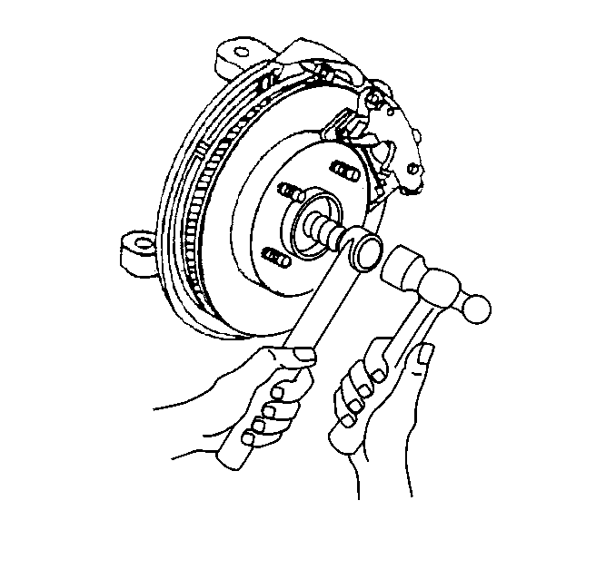
Important: Do not attempt to remove the wheel drive shaft at this time.
Important: After the lower ball joint is loose from the knuckle, simultaneously push the wheel drive shaft in toward the differential carrier in order to allow room for the knuckle and brake assembly to be removed.
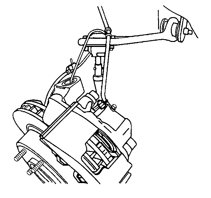
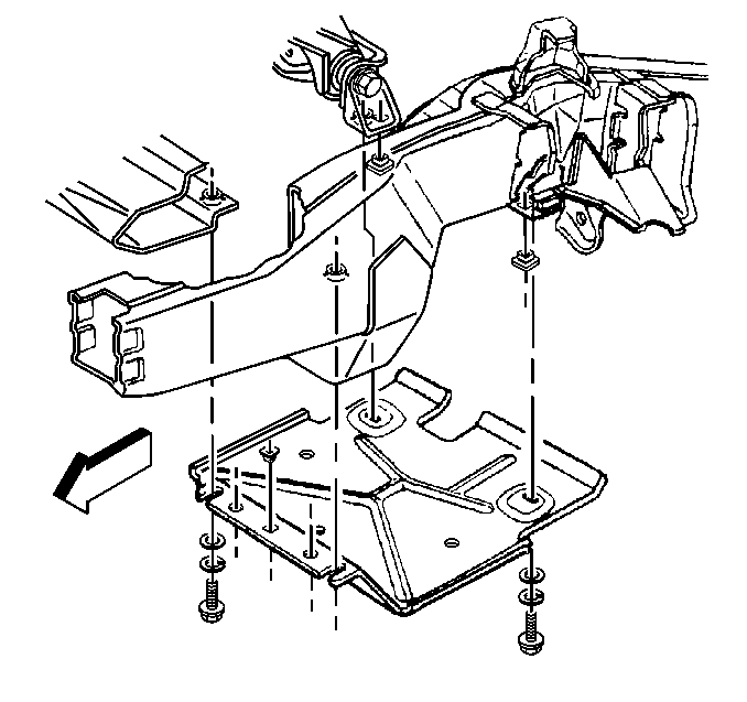
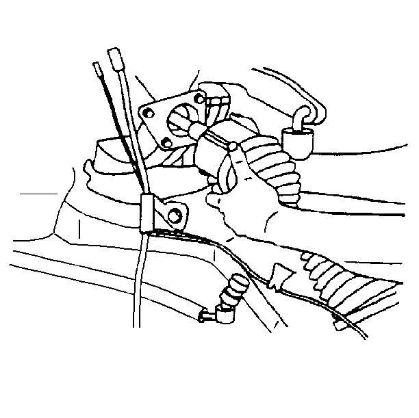
Important: Do not damage the differential carrier axle seals during removal.
Installation Procedure
Do not lubricate or damage the differential carrier axle seals during installation.
- In order to prevent damage to the boot, cover the following components with a shop towel:
- Install the wheel drive shaft to the differential carrier.
- Raise the safety stand to support the weight of the lower control arm.
- Assemble the lower ball joint. Refer to Lower Control Arm Ball Joint Replacement in Front Suspension.
- Install the upper ball joint. Refer to Upper Control Arm Ball Joint Replacement in Front Suspension.
- Install the lower shock mount. Refer to Shock Absorber Replacement in Front Suspension.
- Install the wheel drive shaft washer and nut.
- Install the ABS bracket located on the top of the upper control arm ball joint.
- Install the support brackets to the upper control arm holding both the ABS wire and the brake hose.
- Install the tires and wheels.
- Remove the safety stands.
- Install the front differential carrier shield.
- Install the front differential carrier shield bolts.
- Remove the strap from the frame.
- Lower the vehicle.
| • | The shock mounting bracket |
| • | The lower control arm ball stud |
| • | All other sharp edges |

| 2.1. | With both hands on the tripot housing, align the splines on the shaft with the differential carrier. |
| 2.2. | Center the drive axle into the differential carrier seal. |
| 2.3. | Firmly push the shaft straight into the differential carrier until the snap ring seats into place. |
Notice: Be careful that the safety stand does not damage or bend any components it may contact.

Important: It will be necessary to slightly start the steering knuckle and brake assembly onto the wheel drive shaft while simultaneously guiding the lower ball stud to its proper location on the steering knuckle.

Notice: Use the correct fastener in the correct location. Replacement fasteners must be the correct part number for that application. Fasteners requiring replacement or fasteners requiring the use of thread locking compound or sealant are identified in the service procedure. Do not use paints, lubricants, or corrosion inhibitors on fasteners or fastener joint surfaces unless specified. These coatings affect fastener torque and joint clamping force and may damage the fastener. Use the correct tightening sequence and specifications when installing fasteners in order to avoid damage to parts and systems.
Tighten
Tighten the nut to 140 N·m (103 lb ft).

Tighten
Tighten the nut to 17 N·m (13 lb ft).
Tighten
Tighten the nut to 17 N·m (13 lb ft).

Tighten
Tighten the bolts to 25 N·m (19 lb ft).
