Removal Procedure
- Raise the vehicle. Refer to Lifting and Jacking the Vehicle in General Information.
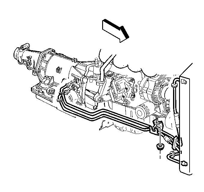
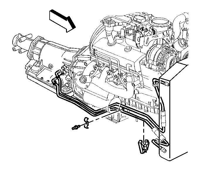
- For vehicles equipped with a 2.2L engine, remove the nut securing the cooling line to the engine.
- For vehicles equipped with a 4.3L engine, remove the clip and stud securing the cooler line to the engine.
- Pull the plastic cap back from the quick connect fitting and down along the cooler line about two inches.
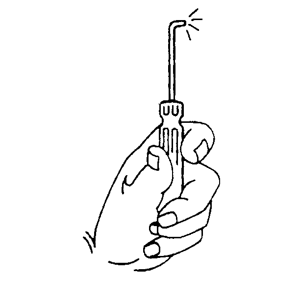
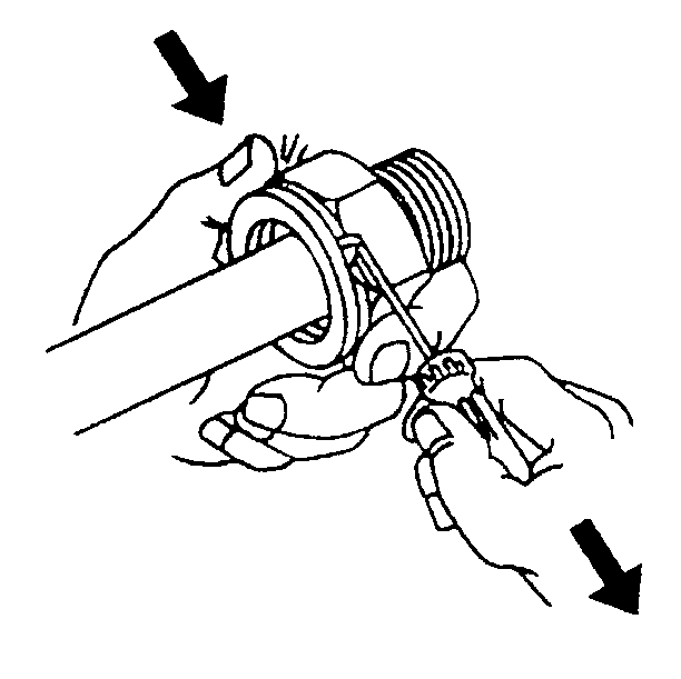
- Using a bent-tip screwdriver, pull on one of the open ends of the retaining ring in order to rotate the retaining ring around the quick connect fitting until the retaining ring is out of position and can be completely removed.
- Remove the retaining ring from the quick connect fitting.
- Discard the retaining ring.
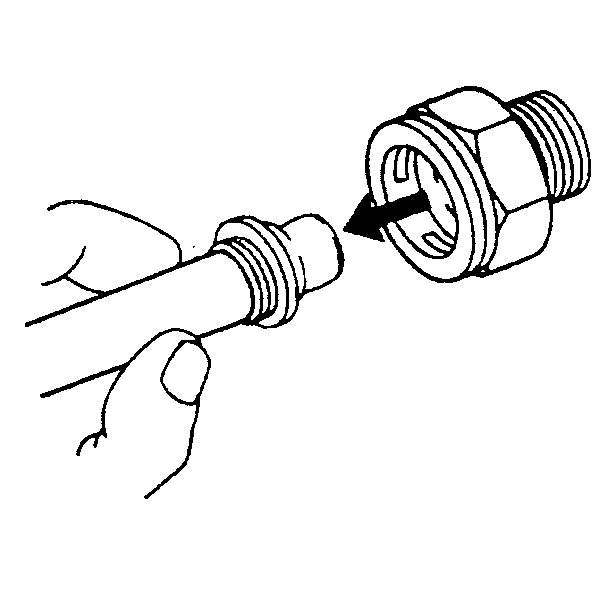
- Pull the cooler line straight out from the quick connect fitting.
- Remove the retaining ring (E-clips) securing the cooler line to the quick connect in order to remove the remaining cooler lines from the remaining quick connect fittings.
- Remove the cooler lines from the vehicle.
Important: Perform the following procedures when removing the retaining ring and cooler line from the quick connect fitting on the transmission.
Installation Procedure
- Install the transmission oil cooler line to the vehicle.
- Install a new retaining ring (E-clip) into the quick connect fitting using the following procedure:
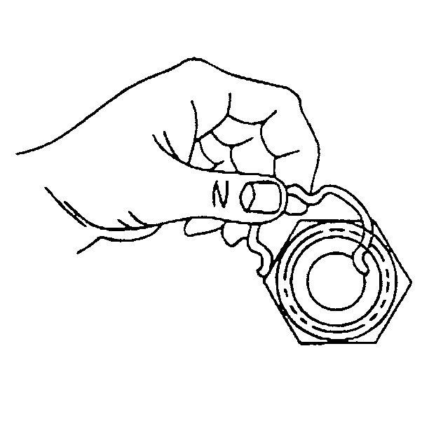
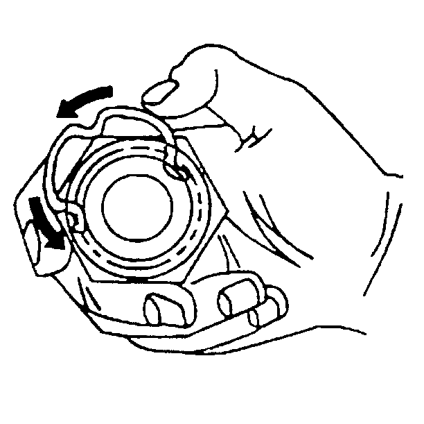
- Hook one of the open ends of the retaining ring in one of the slots in the quick connect fitting.
- Rotate the retaining ring around the fitting until the retaining ring is positioned with all three ears through the three slots on the fitting.
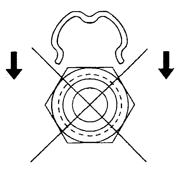
- Do not install the new retaining ring onto the fitting by pushing the retaining ring.
- Ensure that the three retaining ring ears are seen from inside the fitting and that the retaining ring moves freely in the fitting slots.
- Install the new retaining ring (E-clip) into the remaining quick connect fittings.
- Install the cooler lines to the vehicle.
- Install the cooler line into the quick connect fitting.
- Insert the cooler line end into the quick connect fitting until a click is either heard or felt.
- Pull back sharply on the cooler line in order to ensure the cooler line is fastened into the quick connect fitting.
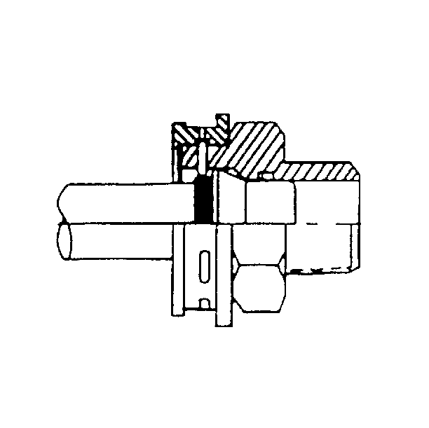
- Position (snap) the plastic cap onto the fitting. Do not manually depress the retaining ring when installing the plastic cap onto the quick connect fitting.
- Ensure that the plastic cap is fully seated against the fitting.
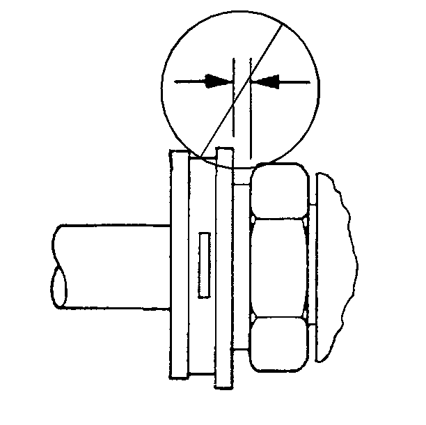
- Ensure that no gap is present between the cap and the fitting.
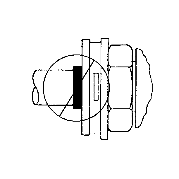
- Ensure that the yellow identification band on the tube is hidden within the quick connect fitting.
- A hidden yellow identification band indicates proper joint seating.
- Install all remaining cooling line ends to the remaining fittings.
- For vehicles equipped with a 4.3L engine, install the stud and clip securing the cooler line to the engine.
- For vehicles equipped with a 2.2L engine, Install the nut securing the oil cooler lines to the engine.
- Lower the vehicle.
Important:
• Inspect all existing fittings and cooler lines for corrosion.
If any of the fittings or cooler line ends are pitted or scared from corrosion,
replace the fitting or cooler line to ensure proper cooler line to fitting
connection. • Do not reuse any of the existing retaining rings that were removed
from the existing quick connect fittings. All retaining rings being installed
must be new. • Ensure the following procedures are performed when installing
the new retaining rings onto the fittings.
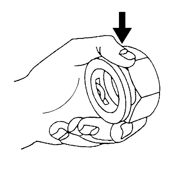
Notice: Ensure that the cooler line being installed has a plastic cap on each end that connects to a quick connect fitting. If no plastic cap exists, or the plastic cap is damaged, obtain a new plastic cap and position on to the cooler line prior to the cooler line installation.

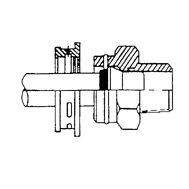
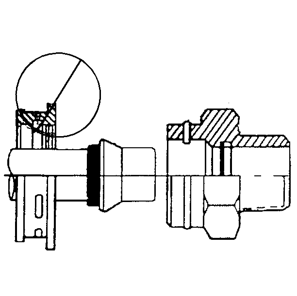
Important: Do not use the plastic cap on the cooler line in order to install the cooler line into the fitting.


Notice: Use the correct fastener in the correct location. Replacement fasteners must be the correct part number for that application. Fasteners requiring replacement or fasteners requiring the use of thread locking compound or sealant are identified in the service procedure. Do not use paints, lubricants, or corrosion inhibitors on fasteners or fastener joint surfaces unless specified. These coatings affect fastener torque and joint clamping force and may damage the fastener. Use the correct tightening sequence and specifications when installing fasteners in order to avoid damage to parts and systems.
Tighten
Tighten the stud to 11 N·m (97 lb in).

Tighten
Tighten the nut to 11 N·m (97 lb in).
