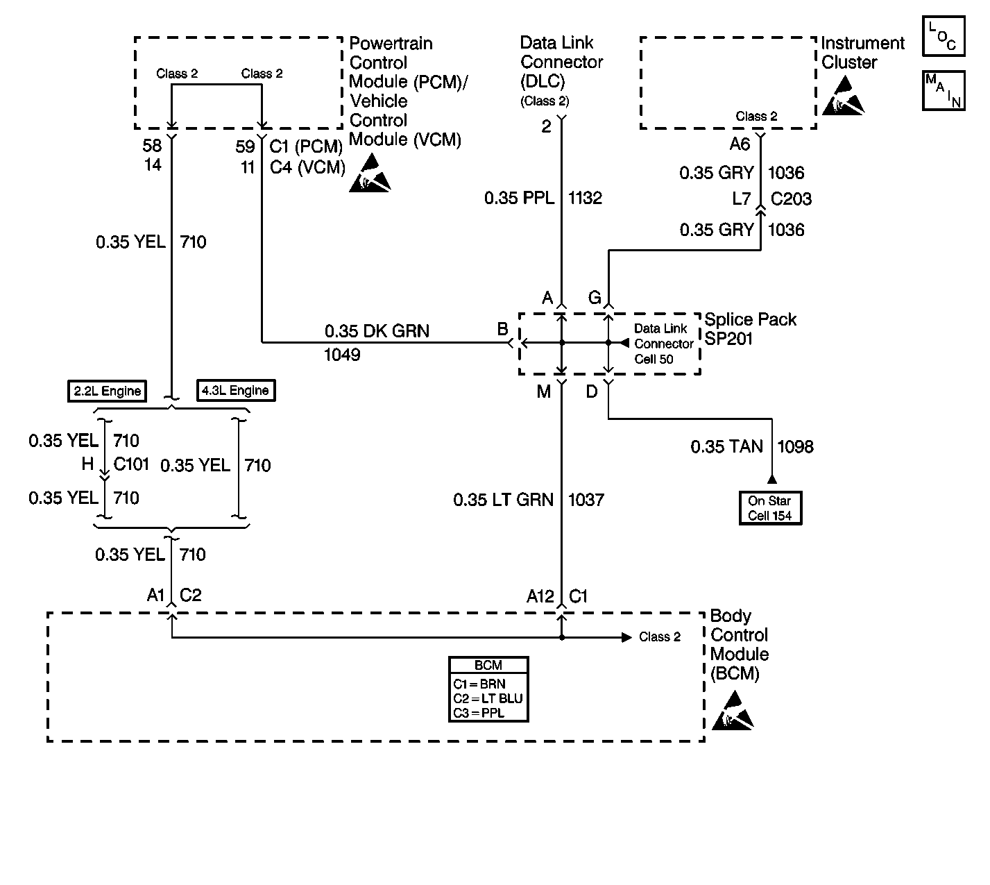
Circuit Description
Operating information and commands are exchanged among the modules on the class 2 serial data circuit. If a critical operating parameter is not received, a module will use a default value. When a module receives a critical operating parameter message from the BCM, the receiving module monitors communication with the BCM. The BCM must send a NODE ALIVE message every 2 seconds. If more than 5 seconds pass without a NODE ALIVE message from the BCM, DTC U1064 will be set by the module that should have received the message.
Conditions for Setting the DTC
| • | The voltage supplied to the module is in the normal operating range (approximately 9-16 volts). |
| • | DTC U1300 and DTC U1301 do not have a current status. |
| • | The vehicle power mode (ignition switch position) requires serial data communication to occur. |
| • | A message from the BCM is not detected for the past 5 seconds. |
Conditions for Clearing the DTC
| • | A current DTC will clear when a NODE ALIVE message from the BCM is detected on the class 2 serial data circuit or at the end of the current ignition cycle. |
| • | A history DTC will clear upon receipt of a scan tool CLEAR DTCs command. |
Step | Action | Value(s) | Yes | No |
|---|---|---|---|---|
1 | Perform the BCM Diagnostic System Check. Refer to Diagnostic System Check - Body Control System in Body Control System. Was a repair completed when the BCM Diagnostic System Check was performed? | -- | Go to Step 6 | Go to Step 2 |
2 | Inspect splice pack SP201 for a poor connection. Repair as necessary. Did you find and repair a poor connection? | -- | Go to Step 6 | Go to Step 3 |
3 |
Did you find and repair a poor connection or defective terminal? | -- | Go to Step 6 | Go to Step 4 |
4 | Test the class 2 serial data circuit for an open between the BCM and SP201. Repair as necessary. Did you find and repair a condition? | -- | Go to Step 6 | Go to Step 5 |
5 | Replace the BCM. Is the repair complete? | -- | Go to Step 8 | -- |
6 |
Does the scan tool display any DTCs that do not begin with a U? | -- | Go to the Applicable DTC Table | Go to Step 7 |
7 | Clear the DTCs using the scan tool. Did you clear the DTCs? | -- | Go to Step 8 | -- |
8 | Select the DISPLAY DTCs function for the BCM. Does the scan tool display any DTCs that do not begin with a U? | -- | Go to the Applicable DTC Table | Go to Step 9 |
9 |
Are all of the DTCs cleared? | -- | System OK | -- |
