Disassembly Procedure
Special Tools
J 8059 Snap Ring Pliers
- Remove the clamps from the boot with a pair of side cutters.
- Use a hand grinder to cut through the swage ring.
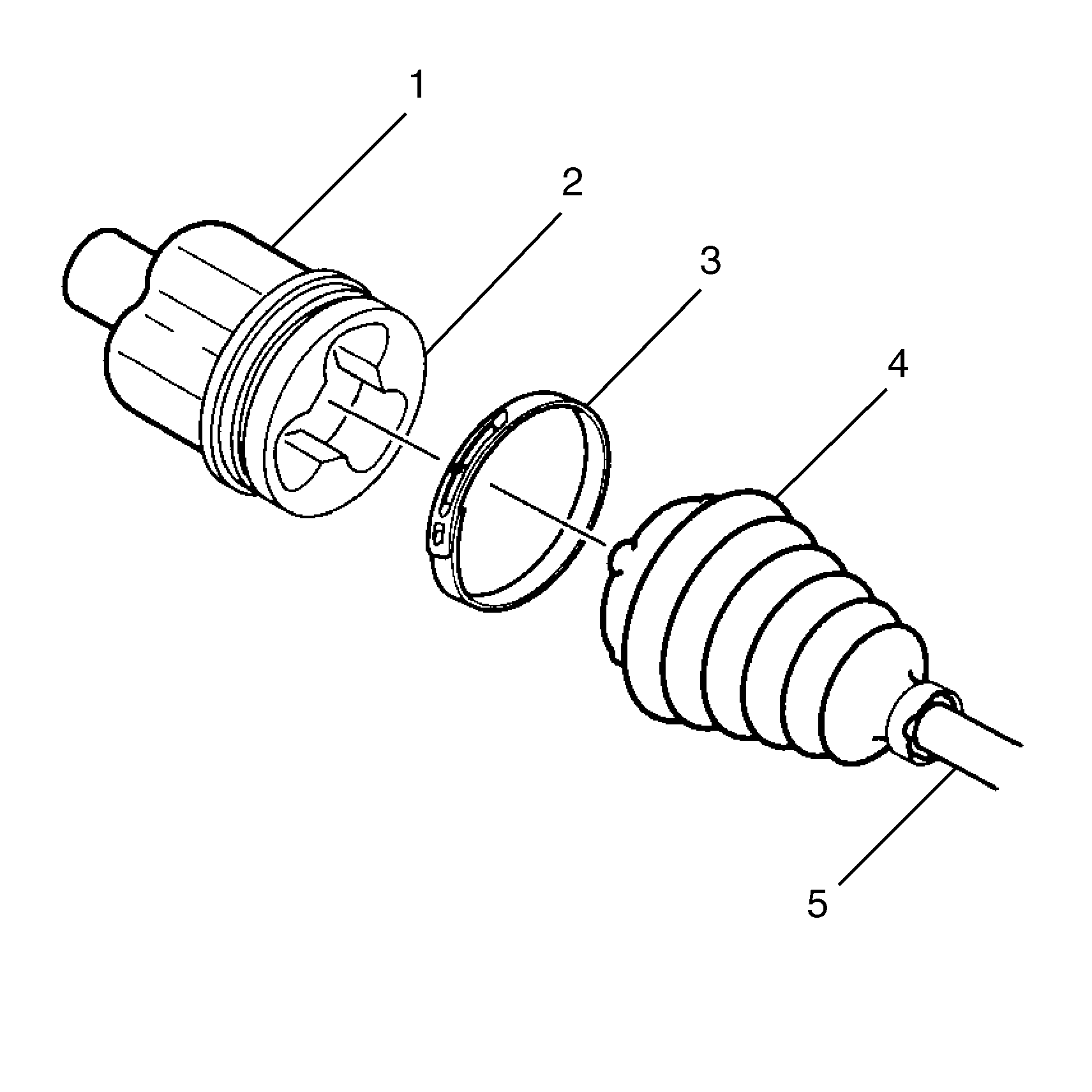
- Remove the tripot housing (1) and the tripot trilobal bushing (2) from the halfshaft bar (5).
- Wipe the grease off of the tripot assembly roller bearings and the housing (1).
- Thoroughly degrease the housing (1) and the tripot trilobal bushing (2).
- Use 320 grit 3M cloth (or equivalent) to remove any evident corrosion in the transmission sealing surface.
- Allow the housing (1) and the tripot trilobal bushing (2) to dry prior to assembly.
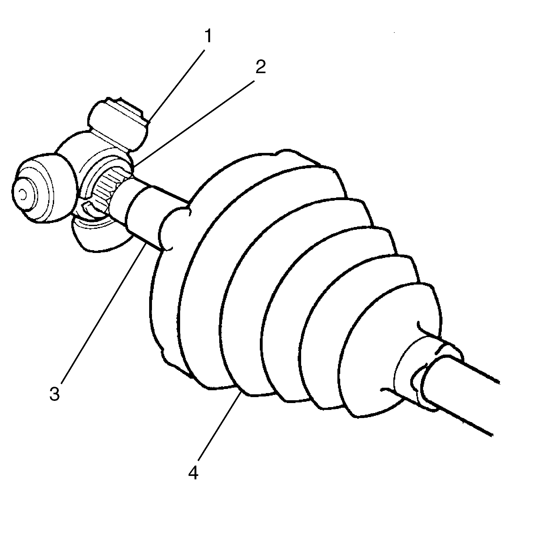
- Compress the tripot boot (4) onto the halfshaft bar (3), away from the spider assembly (1).
- Spread the spacer rings using J 8059 (or equivalent) to remove the spider assembly.
- Remove the following items:
- Clean the halfshaft bar. Use a wire brush to remove any rust in the boot mounting area (grooves).
- Inspect the following items:
- Check the tripot housing for unusual wear, cracks, or other damage.
- Replace any damaged parts.
Important: Do not damage the tripot housing (1).
Important: Handle the tripot spider assembly (1) with care. Tripot balls and needle rollers may separate from the spider trunnion if the tripot balls and needle rollers are not handled carefully.
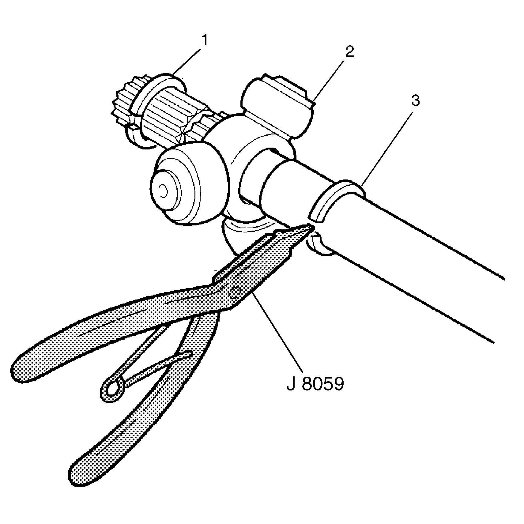
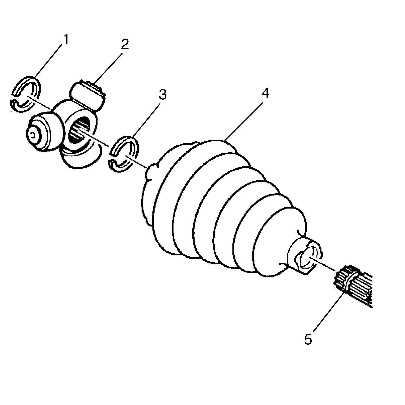
| • | The spacer ring (1) |
| • | The spider assembly (2) |
| • | The second spacer ring (3) |
| • | The tripot boot (4) |
| • | The needle rollers |
| • | The needle bearings |
| • | The trunnion |
Assembly Procedure
Tools Required
| • | J 41048 Swage Clamp Tool |
| • | J 35566 Large Seal Retaining Clamp Tool |
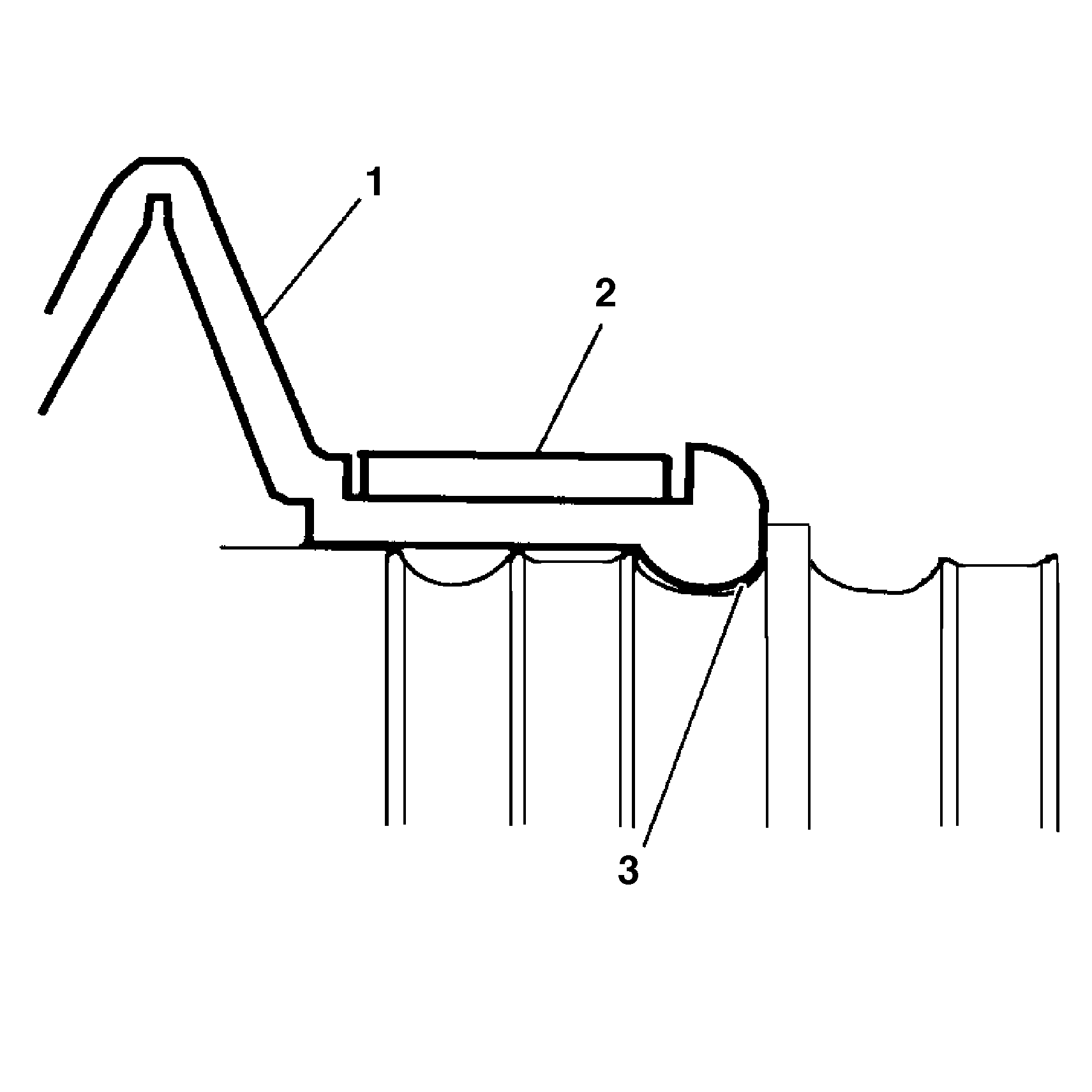
- Slide the new small swage clamp (2) and the boot (1) to the proper position (3) on the halfshaft bar.
- Install the new swage clamp onto the neck of the boot. Do not swage.
- Position the neck of the boot in the boot groove on the halfshaft bar.
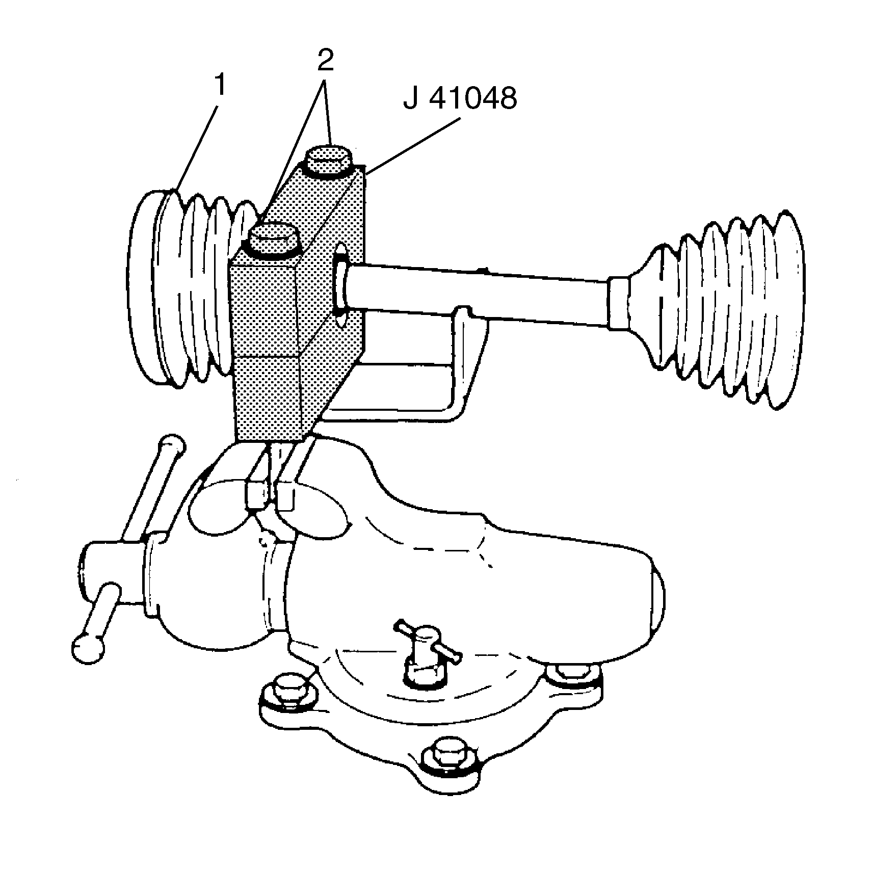
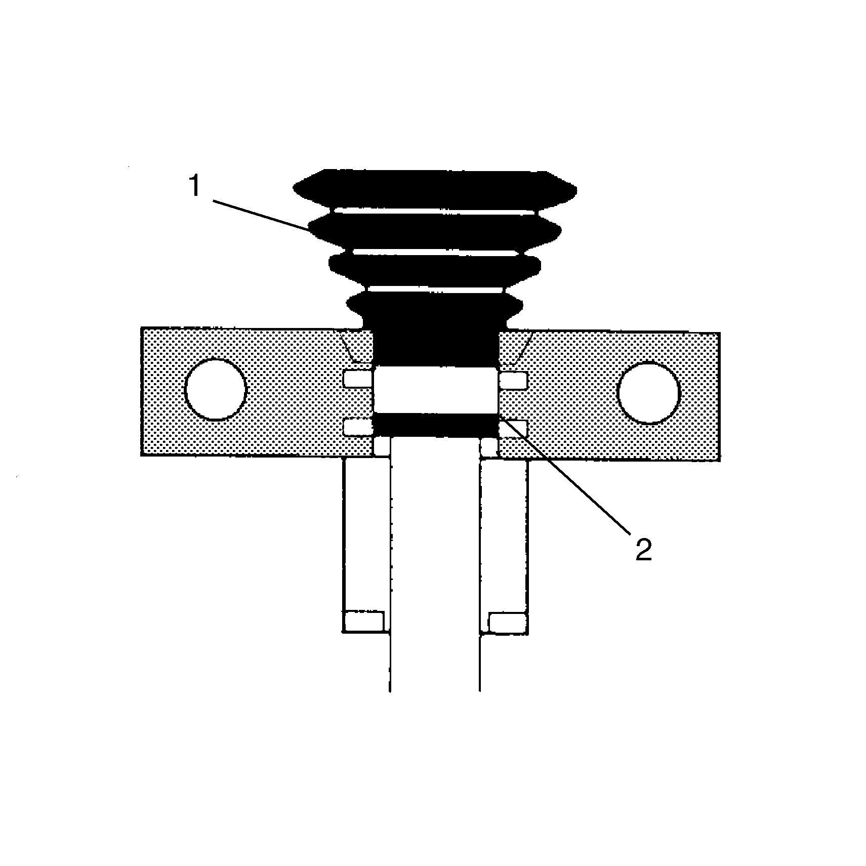
- In order to swage the swage clamp, position the inboard end (1) of the halfshaft assembly in J 41048 .
- Align the swage clamp (2) within J 41048 .
- Place the top half of the J 41048 on the bottom half.
- Check to make sure there are no pinch points on the boot before proceeding.
- Insert the bolts (2).
- Tighten the bolts (2) by hand until snug.
- Align the following items:
- Loosen the bolts.
- Separate the dies.
- Check the swage clamp for any "lip" deformities.
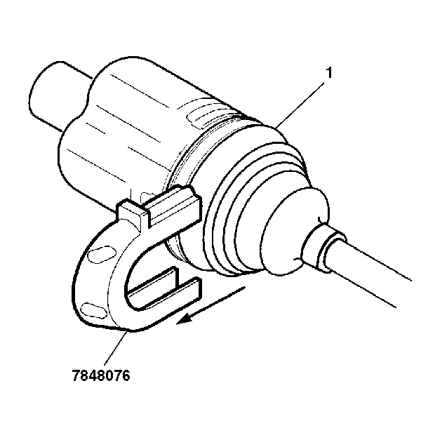
- Install the convolute retainer over the boot capturing four convolutions.
- Install the spacer ring (2) and spider assembly (1) onto the halfshaft bar (3).
- Install the other spacer ring in the groove at the end of the halfshaft bar. Ensure that the rings are fully seated.
- Pack the boot and housing with the grease supplied in the kit. The amount of grease supplied in this kit has been pre-measured for this application.
- Place the large retaining clamp (2) on the boot.
- Place the housing (1) and the tripot trilobal bushing over the spider assembly (3).
- Install the boot onto the tripot trilobal bushing.
- Inspect the inboard stroke position (see diagram).
- Check the inboard stroke position.
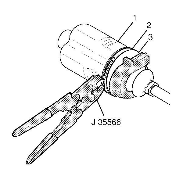
- Secure the large retaining clamp (2) and the boot (3) to the housing (1) using J 35566 .
- Remove the convolute retainer from the boot (1).

Notice: Use the correct fastener in the correct location. Replacement fasteners must be the correct part number for that application. Fasteners requiring replacement or fasteners requiring the use of thread locking compound or sealant are identified in the service procedure. Do not use paints, lubricants, or corrosion inhibitors on fasteners or fastener joint surfaces unless specified. These coatings affect fastener torque and joint clamping force and may damage the fastener. Use the correct tightening sequence and specifications when installing fasteners in order to avoid damage to parts and systems.
| • | The boot |
| • | The housing |
| • | The swage clamp |
Tighten
Each bolt 180 degrees at a time, using a ratchet wrench. Alternate between each bolt until both sides are bottomed.
Important: If deformities exist in the swage clamp, place the swage clamp back into J 41048 . Ensure the swage clamp covers the whole swaging area. Re-swage the swage clamp.
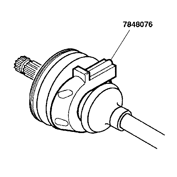
Important: Assemble the joint with the convolute retainer in the correct position. Assemble the joint to meet the specified dimension to avoid boot damage.
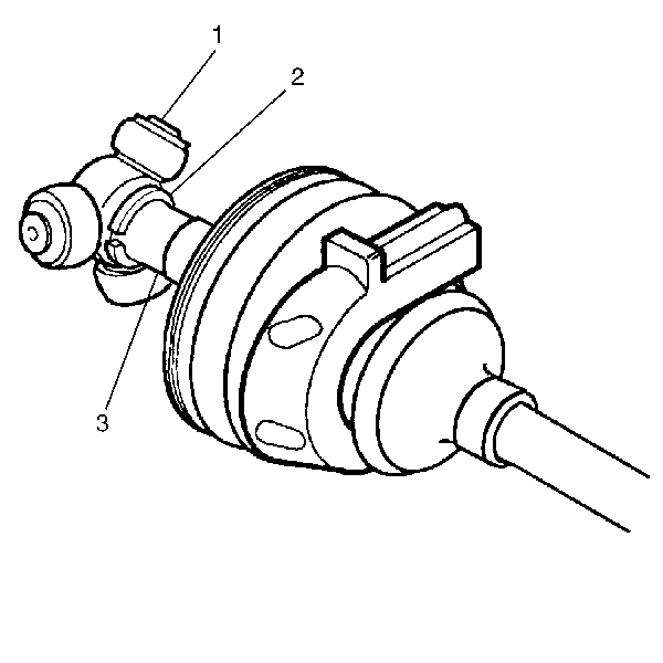
Important: Ensure that the rings are fully seated.
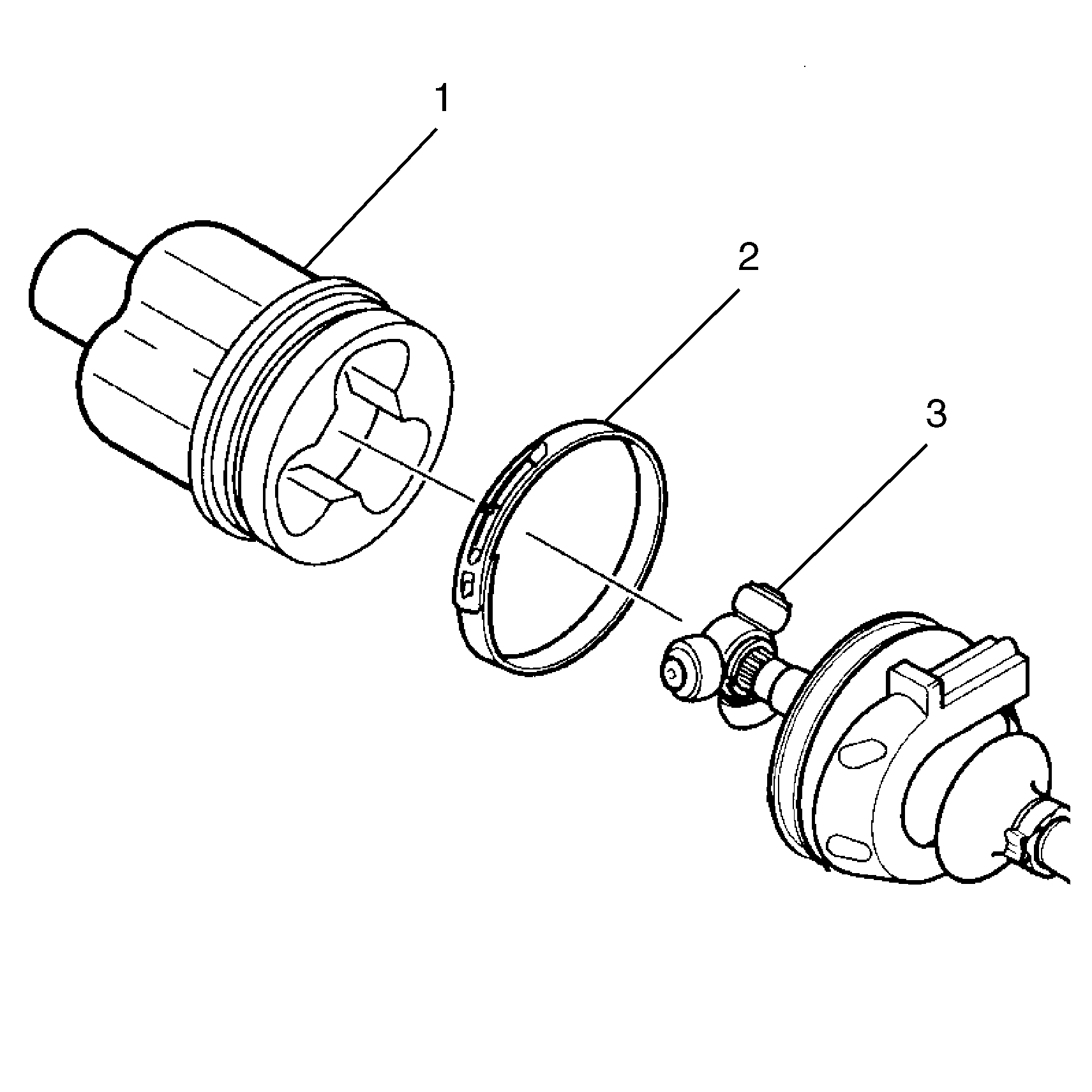
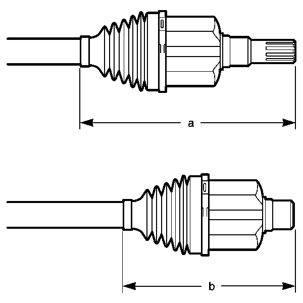
| • | For male tripot housing assembly: dimension a = 280 mm (11 in). |
| • | For female tripot housing assembly: dimension b = 228 mm (9 in). |

