FRONT AXLE GROWL/WHINE NOISE IN 2WD, GONE IN 4WD HI

SUBJECT: FRONT AXLE GROWL/WHINE NOISE IN 2WD, GONE IN 4WD HI (DIAGNOSE/REPLACE BUSHINGS/GRIND CONTACT POINTS)
MODELS: 1993 T VEHICLES
CONDITION:
--------- Some 1993 T-trucks may exhibit a front axle growl/whine type noise while in 2WD, emanating from the front left side of the vehicle. This noise may appear to be louder when the vehicle is cold and diminish when the vehicle warms up. When shifted into 4WD HI, the growl/whine noise goes away.
Important
BEFORE IMPLEMENTING THIS FIX, BE SURE TO VERIFY THAT THE NOISE CONDITION OCCURS IN 2WD ONLY AND GOES AWAY WHEN THE TRANSFER CASE IS SHIFTED INTO 4WD HI. THIS BULLETIN IS INTENDED TO CORRECT ONLY THIS CONDITION.
CAUSE/CORRECTION: ---------------- This growl/whine noise complaint may be caused by one or both of the following conditions:
1. Noise path created due to hardened rubber in the two front axle differential carrier assembly bushings. Noise level is increased during cold ambient temperatures. Repair: Replace the two hardened rubber bushings with softer rubber bushings.
2. Front axle differential carrier assembly mounting bracket may contact axle carrier assembly. This contact creates a metal-to-metal "ground out" noise path condition. Repair: Grind metal contact points to provide clearance.
SERVICE PROCEDURE
Tools Required:
J 33791 Carrier Bushing Remover and Installer (three pieces: J 33791-1, J 33791-2, J 33791-3)
J 21474-18 3/8 inch Nut
J 21474-19 Puller Bolt/Thrust Bearing
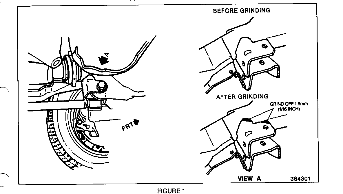
1. Place vehicle on hoist and locate the front axle differential carrier lower mounting bracket. Inspect for possible contact of lower bracket to carrier assembly at two locations (see Figure 1, View A).
2. Remove front axle differential carrier assembly. Refer to 1993 Service Manual, Section 4C-6 through 4C-8.
3. If lower bracket contacted carrier assembly, hand grind 1.5 mm (1/16 in.) from contact points (see Figure 1, View A).
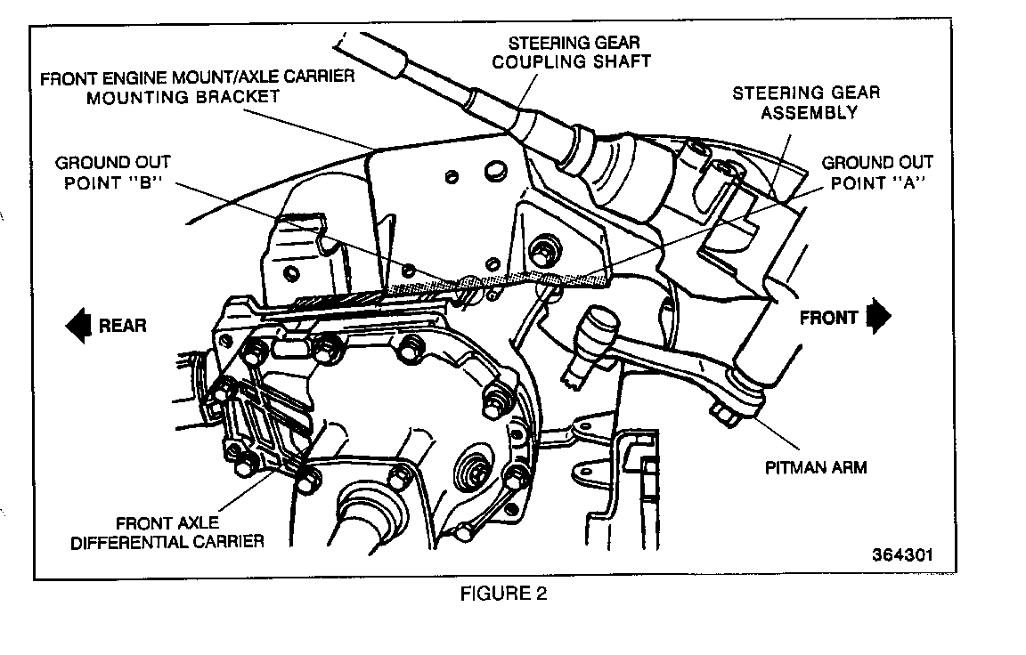
4. Place carrier assembly on workbench. Inspect for groundout witness marks on top of carrier assembly casting. Ground out point "A" is located on the forward (inboard) edge of differential carrier ear/upper bushing receptacle. Ground out point "B" is located on the forward top body rib of differential carrier. (see Figure 2, Ground Out Points "A" and "B")
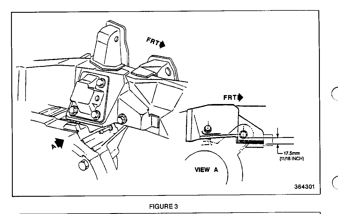
5. For ground out point "A", grinding of the front axle carrier mounting bracket may be necessary. Measure from bottom of upper bushing mounting hole to the bottom edge of bracket. Length of measurement should be 17.5 mm (11/16 in.) vertically (see Figure 3, View A). If measurement is greater than 17.5 mm (11/16 in.) vertically, grind off metal from the bracket bottom edge (see Figure 2, shaded edge of bracket in the Ground Out Point "A" area) to achieve the proper 17.5 mm (11/16 in.) length along this bracket edge.
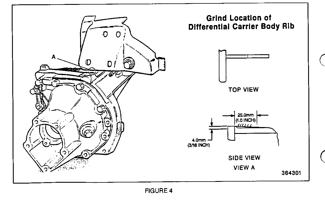
6. For ground out point "B", DO NOT grind any metal from the axle carrier mounting bracket bottom edge, in the vicinity of the engine mount (see Figure 2, Ground Point "B"). Instead, hand grind the forward top body rib casting, on the front axle differential carrier, 4 mm (3/16 in.) deep, 25 mm (1 in.) long to achieve the required clearance (see Figure 4, View A).
7. Touch up the grind area on the bracket with paint to prevent rust.
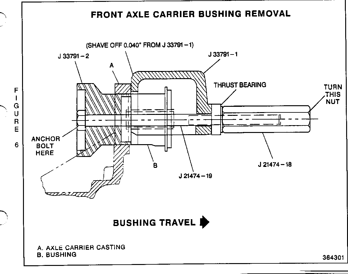
8. Return to the carrier assembly to remove the two old bushings using Kent-Moore tool J 33791 (CARRIER BUSHING REMOVER AND INSTALLER). This tool consists of 3 pieces-use only J 33791-1 and J 33791-2. Use with tools J 21474-18 (3/8" NUT) and J 21474-19 (3/8" PULLER BOLT/THRUST BEARING) or an equivalent 3/8" dia. bolt at 7 3/4 inches (20 mm) in length with nut (see Figure 6).
Note: If tool J 33791-1 was purchased prior to 1993, 0.040 inch must be shaved off of the flat end (end that mounts up flush to carrier). This is necessary to ensure that the tool mounts properly between the bushing flange and carrier (without hammering into place) and that it mounts up flush to the carrier bushing receiver
Note: Kent-Moore tool J 33791 purchased after March, 1993 will have the 0.040 inch adjustment and will be labeled as J 33791-1-A.
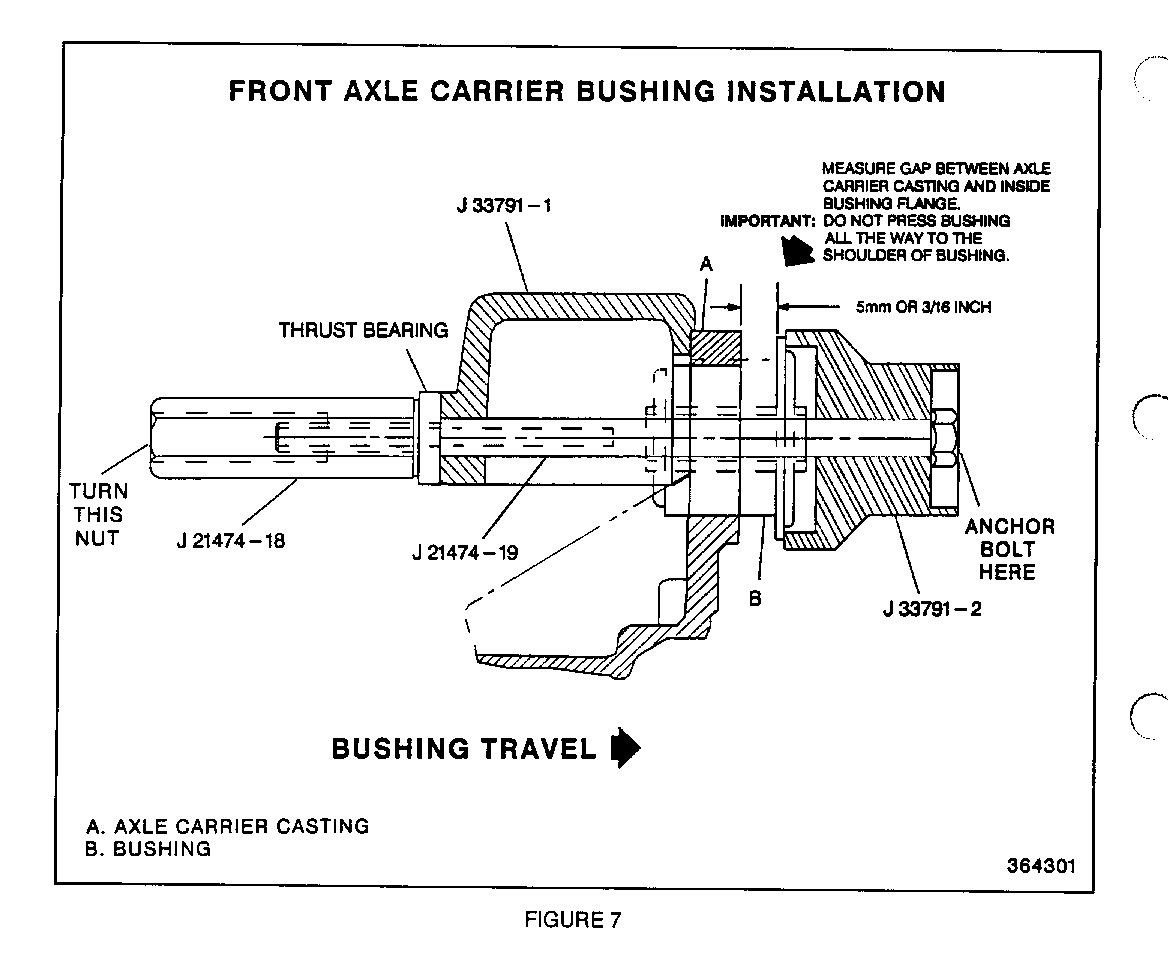
9. Install two new bushings (P/N 26022006) into the carrier assembly with tool J 33791 (see Figure 7).
Important
Measure bushing gap during new bushing installation. DO NOT set in all the way to the shoulder on the bushing. Instead, measure bushing gap with a ruler so the inside of bushing flange to inside of carrier receiver equals 5 mm (3/16 inch). DO NOT use J 33791-3 for this measurement. The correct bushing gap is necessary for proper centering of the axle assembly upon reinstallation.
10. Reinstall front axle differential carrier assembly. Refer to 1993 Service Manual, Section 4C-6 through 4C-8.
Important
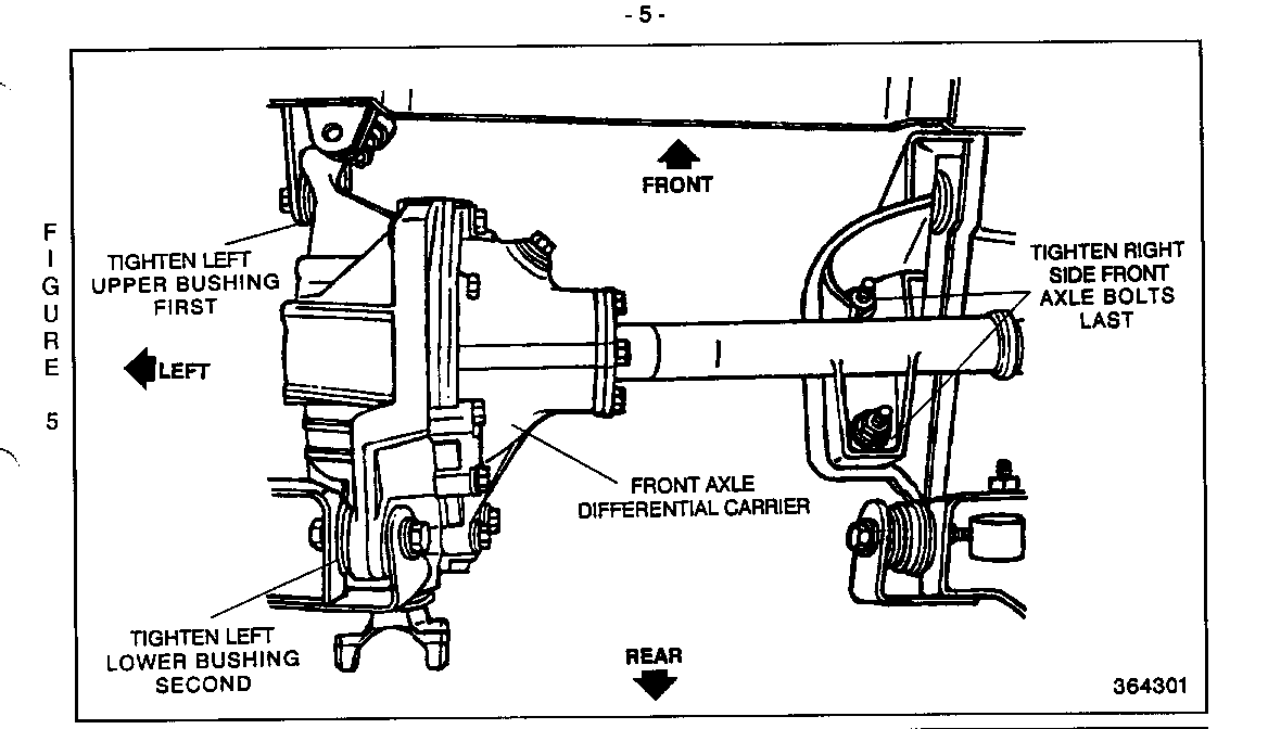
Tighten carrier assembly in place using the correct tightening sequence. Tighten left upper bushing bolt/nut first, tighten left lower bushing bolt/nut second, then tighten right side front axle bolts last. (See Figure 5).
This bushing and groundout repair procedure will eliminate the 2WD growl/whine noise for the majority of customer vehicles. If after this repair and during the road test, the growl/whine noise is still present in 2WD, contact Technical Assistance to obtain further instructions.
SERVICE PARTS INFORMATION
Part Description Quantity Number ----------- -------- ------ 26022006 Front Axle Differential Carrier 2 Bushing
Parts are currently available through GMSPO.
WARRANTY INFORMATION
For vehicles repaired under warranty, use:
Labor Description Labor Time Op ----------- ---------- ----- F2122 Carrier Assy R&R See Applicable Labor Time Guide
General Motors bulletins are intended for use by professional technicians, not a "do-it-yourselfer". They are written to inform those technicians of conditions that may occur on some vehicles, or to provide information that could assist in the proper service of a vehicle. Properly trained technicians have the equipment, tools, safety instructions and know-how to do a job properly and safely. If a condition is described, do not assume that the bulletin applies to your vehicle, or that your vehicle will have that condition. See a General Motors dealer servicing your brand of General Motors vehicle for information on whether your vehicle may benefit from the information.
