Intake Manifold Replacement Upper
Removal Procedure
- Remove the air cleaner outlet duct from the throttle body. Refer
to
Air Cleaner Outlet Duct Replacement
In Engine Controls.
- Remove the air cleaner assembly. Refer to
Air Cleaner Assembly Replacement
in Engine Controls.
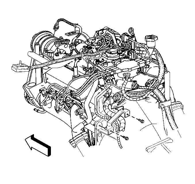
- Disconnect the following
electrical connectors:
| • | The A/C pressure switch, if equipped |
| • | The throttle position (TP) sensor |
| • | The idle air control (IAC) motor |
| • | The fuel meter body assembly connector |
| • | The manifold absolute pressure (MAP) sensor |
| • | The EVAP canister purge solenoid valve |
- Remove the EVAP canister purge solenoid valve. Refer to EVAP Canister Purge Solenoid Valve Replacement
in Engine Controls.
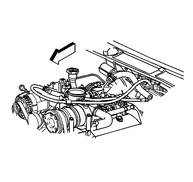
- Disconnect the vacuum
hose from the intake manifold, if equipped with A/C.
- Remove the vacuum brake booster hose.
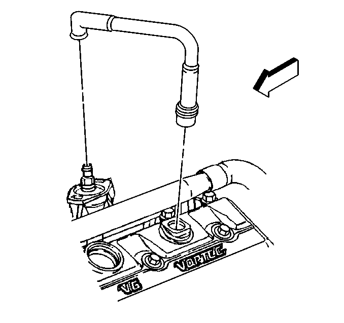
- Remove the PCV valve hose
assembly form the intake manifold and the valve rocker arm cover.
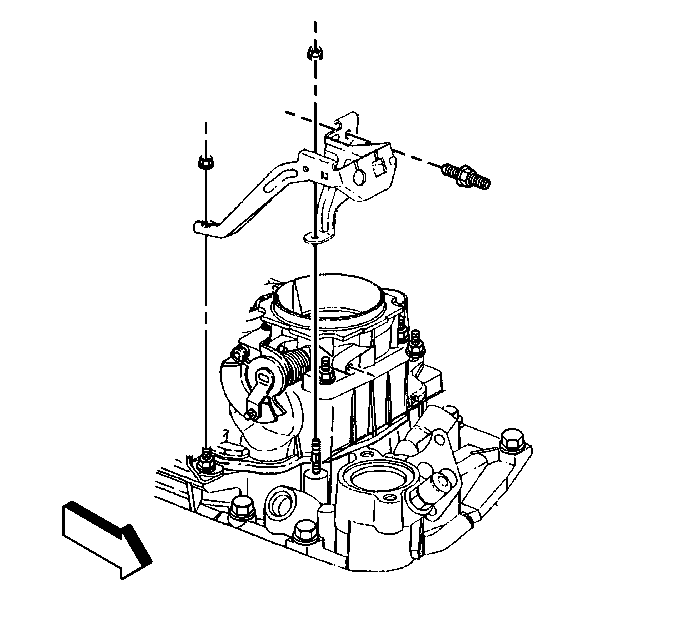
- Disconnect the accelerator
control cable from the throttle shaft and the accelerator cable bracket. Refer
to
Accelerator Control Cable Replacement
in Engine Controls.
- Disconnect the cruise control cable, if equipped from the throttle
shaft and the accelerator cable bracket. Refer to
Cruise Control Cable Replacement
in Cruise Control.
- Remove the accelerator cable bracket from the throttle body and
the intake manifold.
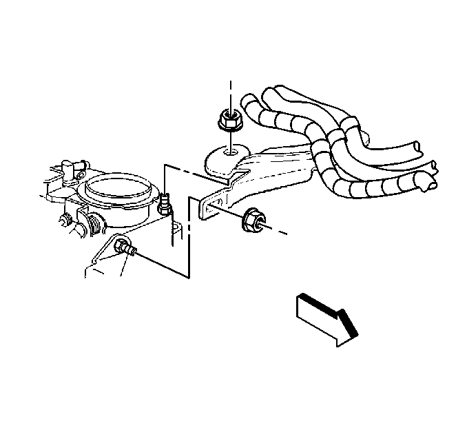
- Remove the accelerator
and cruise control cable bracket from the throttle body.
Leave the accelerator and cruise control cables and the engine wiring
harness on the bracket.
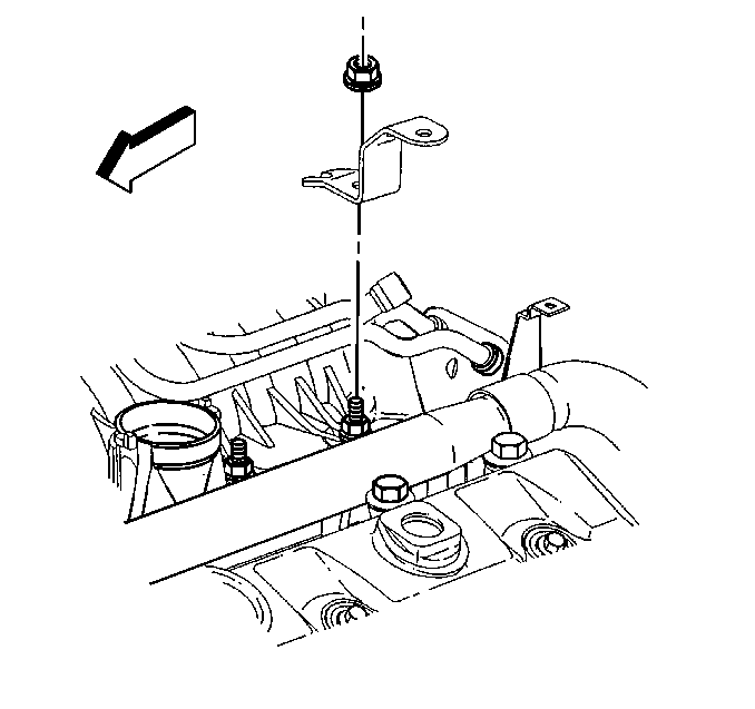
- Remove the bracket for
the engine wiring harness from the intake stud.
- Remove the fuel lines from the fuel meter body assembly. Refer
to
Fuel Hose/Pipes Replacement - Engine Compartment
in Engine Controls.
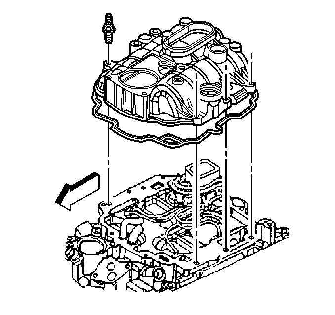
- Remove the upper intake
manifold. Refer to
Intake Manifold Disassemble
.
- Clean all sealing surfaces. Refer to Intake Manifold Clean and Inspect
.
Installation Procedure

- Install the upper intake
manifold. Refer to
Intake Manifold Assemble
.
- Install the fuel lines to the fuel meter body assembly. Refer
to
Fuel Hose/Pipes Replacement - Engine Compartment
in Engine Controls.

- Install the bracket for
the engine wiring harness on the lower intake manifold stud.
Notice: Use the correct fastener in the correct location. Replacement fasteners
must be the correct part number for that application. Fasteners requiring
replacement or fasteners requiring the use of thread locking compound or sealant
are identified in the service procedure. Do not use paints, lubricants, or
corrosion inhibitors on fasteners or fastener joint surfaces unless specified.
These coatings affect fastener torque and joint clamping force and may damage
the fastener. Use the correct tightening sequence and specifications when
installing fasteners in order to avoid damage to parts and systems.
- Install the engine
wiring harness bracket nut.
Tighten
Tighten the engine wiring harness bracket nut to 12 N·m
(106 lb in).

- Install the accelerator
and cruise control cable bracket to the throttle body.
- Install the accelerator and cruise control cable bracket nuts.
Tighten
Tighten the accelerator and cruise control cable bracket nuts to 9 N·m
(80 lb in).

- Install the accelerator
control cable bracket to the throttle body and the intake manifold.
Tighten
Tighten the accelerator control cable bracket studs and nuts to 12 N·m
(106 lb in).
- Install the cruise control cable, if equipped to the throttle
shaft and the bracket. Refer to
Cruise Control Cable Replacement
in Cruise Controls.
- Install the accelerator control cable to the throttle shaft and
the bracket. Refer to
Accelerator Control Cable Replacement
in Engine Controls.
- Install the EVAP canister purge solenoid valve. Refer to EVAP Canister Purge Solenoid Valve Replacement
in Engine Controls.

- Connect the PCV valve
hose assembly to the intake manifold and the valve rocker arm cover.

- Connect the vacuum hose
to the intake manifold, if equipped with A/C.
- Install the vacuum brake booster hose to the intake manifold.

- Connect the following
electrical connectors:
| • | The A/C pressure switch, if equipped |
| • | The throttle position (TP) sensor |
| • | The idle air control (IAC) motor |
| • | The fuel meter body assembly connector |
| • | The manifold absolute pressure (MAP) sensor |
| • | The EVAP canister purge solenoid valve |
- Install the air cleaner assembly. Refer to
Air Cleaner Assembly Replacement
in Engine Controls.
- Install the air cleaner outlet duct to the throttle body assembly.
Refer to
Air Cleaner Outlet Duct Replacement
in Engine Controls.
Intake Manifold Replacement Lower
Removal Procedure
- Disconnect the battery negative cable. Refer to
Battery Replacement
in Engine Electrical.
- Remove the air cleaner outlet duct from the throttle body. Refer
to
Air Cleaner Outlet Duct Replacement
in Engine Controls.
- Remove the air cleaner assembly. Refer to
Air Cleaner Assembly Replacement
in Engine Controls.
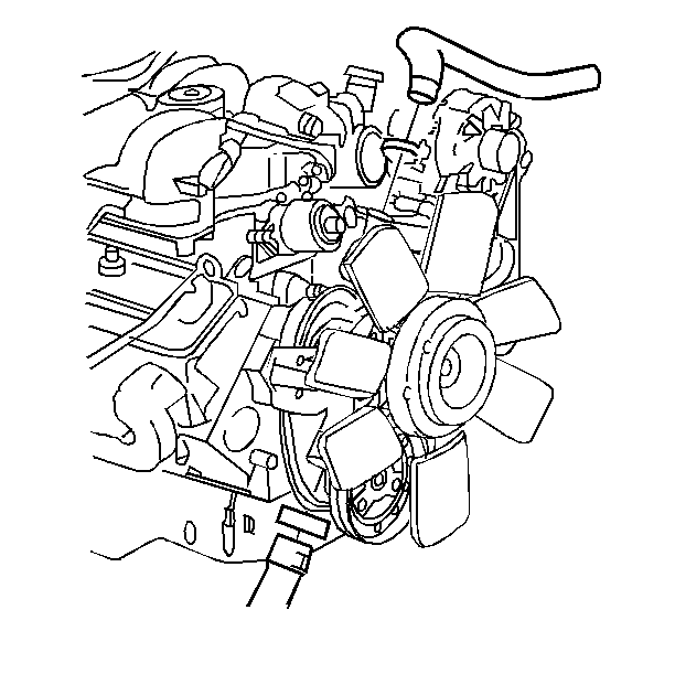
- Drain the cooling system.
Refer to
Cooling System Draining and Filling
in Engine Cooling.
- Remove the radiator inlet hose at the water outlet.
- Remove the heater hose from the intake manifold.
- Remove the water pump inlet hose form the intake manifold.

- Disconnect the accelerator
control cable from the throttle shaft and the accelerator cable bracket. Refer
to
Accelerator Control Cable Replacement
in Engine Controls.
- Disconnect the cruise control cable, if equipped from the throttle
shaft and the accelerator cable bracket. Refer to
Cruise Control Cable Replacement
in Cruise Control.
- Remove the accelerator cable bracket from the throttle body and
the intake manifold.

- Remove the accelerator
and the cruise control cable bracket from the throttle bracket.
Leave the accelerator and cruise control cables and the wiring harness
on the bracket.
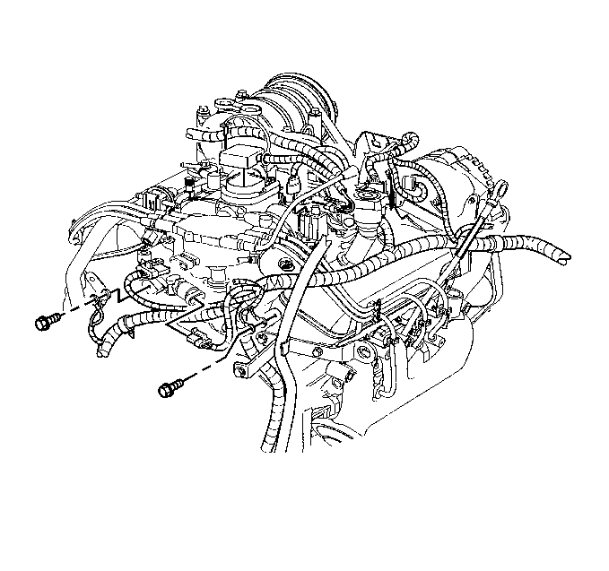
- Remove the following electrical
connectors:
| • | The fuel meter body assembly |
| • | The EVAP canister purge solenoid valve |
| • | The idle air control (IAC) motor |
| • | The throttle position (TP) sensor |
| • | The A/C compressor high pressure switch, if equipped |
| • | The A/C clutch switch, if equipped |
| • | The exhaust gas recirculation (EGR) valve |
| • | The engine coolant temperature (ECT) sensor |
| • | The ignition control module (ICM) |
- Remove the engine wiring harness from the retainers.
- Move the engine wiring harness aside.
- Remove the distributor. Refer to
Distributor Replacement
in Engine Electrical.
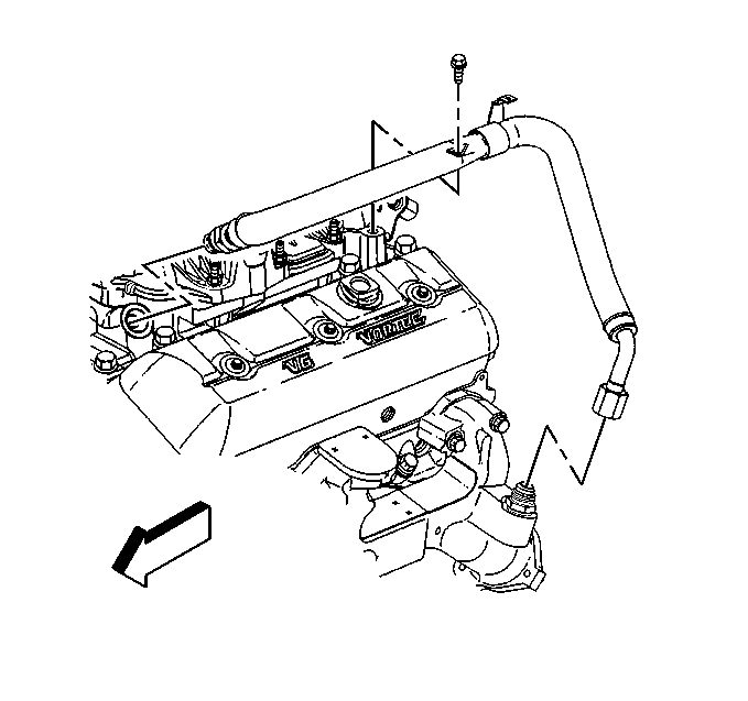
- Remove the exhaust gas
recirculation (EGR) valve inlet pipe from the intake and exhaust manifold.
- Disconnect the fuel supply and return pipes at the rear of the
intake manifold. Refer to
Fuel Hose/Pipes Replacement - Engine Compartment
in Engine Controls.

- Disconnect the vacuum
hose from the intake manifold, if equipped with A/C.
- Disconnect the vacuum brake booster hose

- Disconnect the PCV hose
assembly from the intake manifold and the valve rocker arm cover.
- Remove the EVAP canister purge solenoid valve. Refer to EVAP Canister Purge Solenoid Valve Replacement
in Engine Controls.
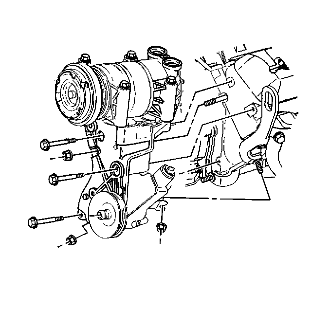
Important: Do not discharge the refrigerant.
- Perform the following in order to remove the left front bolt for the
intake manifold:
| 22.2. | Loosen the nut for the power steering pump rear bracket at the
side of the engine. |
| 22.3. | Remove the secondary air injection (AIR) reactor pipe bracket
nut from the power steering pump rear bracket front stud, if equipped. |
| 22.4. | Remove the nut for the power steering pump rear bracket at the
front of the engine. |
| 22.5. | Remove the bolts and the nut for the power steering pump mounting
bracket. |
| 22.6. | Leave the A/C compressor, if equipped, and the power steering
pump on the power steering pump mounting bracket. |
| 22.7. | Slide the power steering pump bracket forward to access the bolt
at the front of the intake manifold. |
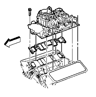
- Remove the lower intake manifold. Refer to Intake Manifold Removal
.
- Clean all sealing surfaces. Refer to Intake Manifold Clean and Inspect
.
Installation Procedure

Notice: Proper lower intake manifold fastener tightening sequence
and torque is critical. Always follow the tightening sequence, and torque
the intake manifold bolts using the 3 step method. Failing to do so may distort
the crankshaft bearing bore alignment and cause damage to the crankshaft bearings.
- Install the lower intake manifold. Refer to Intake Manifold Installation
.

- Position the power steering
pump mounting bracket.
- Loosely install the power steering pump mounting bracket bolts
and nuts.
Notice: Use the correct fastener in the correct location. Replacement fasteners
must be the correct part number for that application. Fasteners requiring
replacement or fasteners requiring the use of thread locking compound or sealant
are identified in the service procedure. Do not use paints, lubricants, or
corrosion inhibitors on fasteners or fastener joint surfaces unless specified.
These coatings affect fastener torque and joint clamping force and may damage
the fastener. Use the correct tightening sequence and specifications when
installing fasteners in order to avoid damage to parts and systems.
- Install the nut
for the power steering pump rear bracket at the front of the engine.
Tighten
Tighten the power steering pump mounting bracket bolts and the power
steering pump rear bracket nuts to 41 N·m (30 lb ft).
- Install the AIR reactor pipe bracket nut to the power steering
pump rear bracket front stud, if equipped.
Tighten
Tighten the AIR reactor pipe bracket nut to 41 N·m (30 lb ft).
- Install the drive belt. Refer to
Drive Belt Replacement
.
- Install the EVAP canister purge solenoid valve. Refer to EVAP Canister Purge Solenoid Valve Replacement
in Engine Controls.

- Connect the vacuum brake
booster hose.
- Connect the vacuum hose to the intake manifold, if equipped with
A/C.

- Install the PCV hose assembly
to the intake manifold and the valve rocker arm cover.
- Install the fuel supply and return pipes to the rear of the intake
manifold. Refer to
Fuel Hose/Pipes Replacement - Engine Compartment
in Engine
Controls.

- Install the exhaust gas
recirculation (EGR) valve inlet pipe to the intake manifold and the exhaust
manifold.
Tighten
- Tighten the EGR valve inlet pipe intake manifold nut to 25 N·m
(18 lb ft).
- Tighten the EGR valve inlet pipe exhaust manifold nut to 30 N·m
(22 lb ft).
- Tighten the EGR valve inlet pipe clamp bolt to 25 N·m
(18 lb ft).
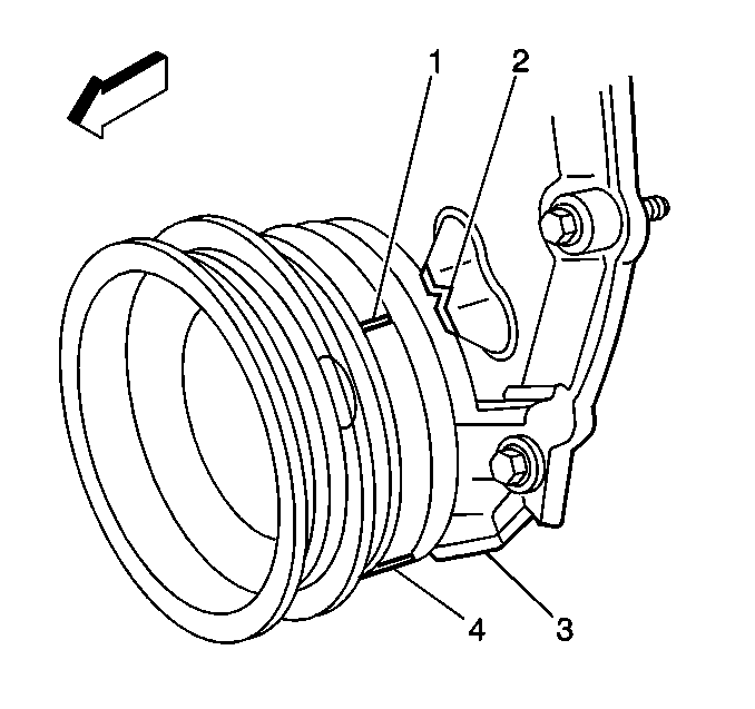
Important: In order to install the distributor for the correct engine timing, position
the engine to number one cylinder top dead center.
- Remove the spark plug for number one cylinder.
- Rotate the crankshaft until number one cylinder is in the compression
stroke.
- Align the two reference marks on the crankshaft balancer (1) and
(4) with the two alignment marks (2) and (3) on the front cover.
- Install the spark plug. Refer to
Spark Plug Replacement
in Engine Electrical.
- Install the distributor. Refer to
Distributor Replacement
in Engine Electrical.

- Position the engine wiring
harness.
- Install the engine wiring harness in the retainers.
- Install the following electrical connectors:
| • | The fuel meter body assembly |
| • | The EVAP canister purge solenoid valve |
| • | The idle air control (IAC) motor |
| • | The throttle position (TP) sensor |
| • | The A/C compressor high pressure switch, if equipped. |
| • | The A/C compressor clutch switch, if equipped. |
| • | The exhaust gas recirculation (EGR) valve |
| • | The engine coolant temperature (ECT) sensor |
| • | The ignition control module (ICM) |

- Install the accelerator
cable and cruise control bracket to the throttle body.
Tighten
Tighten the accelerator cable and cruise control bracket nuts to 9 N·m
(80 lb in).

- Install the accelerator
cable bracket to the intake manifold and the throttle body.
Tighten
Tighten the accelerator cable bracket studs and nuts to 12 N·m
(106 lb in).
- Install the accelerator control cable to the bracket and the throttle
shaft. Refer to
Accelerator Control Cable Replacement
in Engine
Controls.
- Install the cruise control cable, if equipped to the bracket and
the throttle shaft. Refer to
Cruise Control Cable Replacement
in Cruise Control.

- Install the water pump
inlet hose to the intake manifold.
- Install the heater hose to the intake manifold.
- Install the radiator inlet hose to the water outlet. Refer to
Radiator Hose Replacement
in Engine Cooling.
- Fill the cooling system. Refer to
Cooling System Draining and Filling
in Engine Cooling.
- Install the air cleaner assembly. Refer to
Air Cleaner Assembly Replacement
in Engine Controls.
- Install the air cleaner outlet duct to the throttle body. Refer
to
Air Cleaner Outlet Duct Replacement
in Engine Controls.
- Connect the battery negative cable. Refer to
Battery Replacement
in Engine Electrical.


