Removal Procedure
- Disconnect the negative battery cable. Refer to Engine Electrical.
- Disable the SIR system. Refer to Disabling the SIR System in SIR.
- Lower the hush and knee bolster. Refer to Knee Bolster Replacement in Instrument Panel.
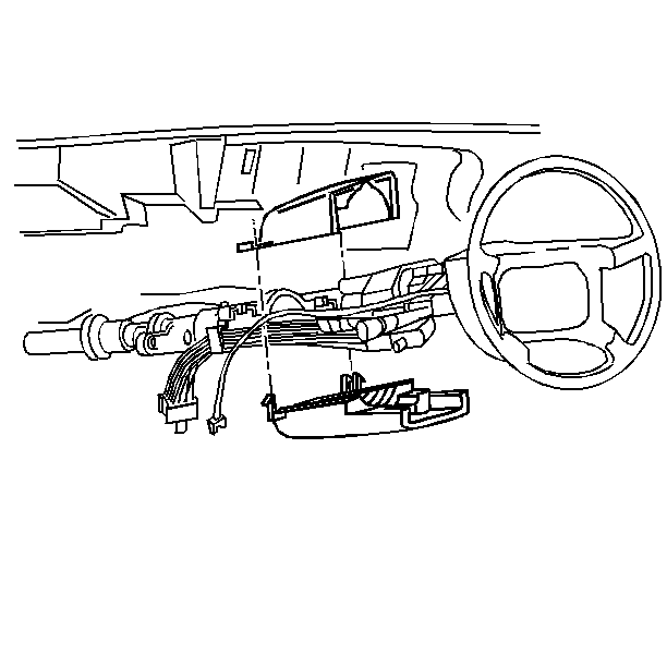
- Remove the screws that retain the lower steering column trim cover to the steering column.
- Remove the lower steering column trim cover by tilting the trim cover down and slide it back in order to disengage the locking tabs..
- Remove the screws that retain the upper steering column trim cover to the steering column.
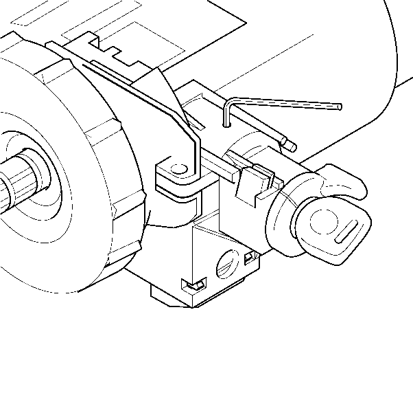
- With the key installed, turn the key to the RUN position.
- Gently lift the upper trim cover up so that you may install an allen wrench into the hole on top of the lock cylinder housing.
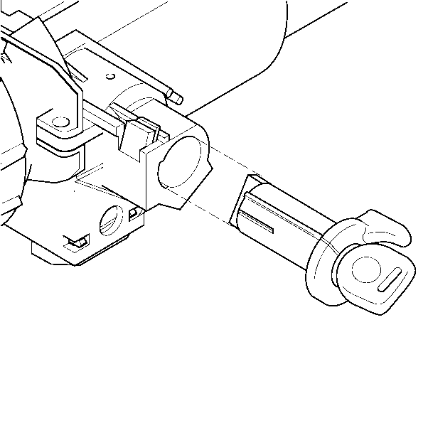
- Slide the lock cylinder out of the lock cylinder housing.
Caution: Refer to SIR Caution in the Preface section.


Push down on the allen wrench to release the tab on the lock cylinder inside the lock cylinder housing.

Installation Procedure
- Align the upper steering column trim cover.
- Install the screws that retain the upper steering column trim cover to the steering column.
- Install the key into the lock cylinder.
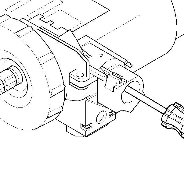
- Use a screwdriver to rotate the lock cylinder housing gear clockwise to the start position - allowing it to spring return into the RUN position.
- Align the lock cylinder and install into the lock cylinder housing.
- Install the lower steering column trim cover.
- Install the screws that retain the lower steering column trim cover to the steering column.
- Install the steering wheel. Refer to Steering Wheel Replacement .
- Install the hush and knee bolster. Refer to Knee Bolster Replacement in Instrument Panel.
- Enable the SIR system. Refer to Enabling the SIR System in SIR.
- Connect the negative battery cable. Refer to Engine Electrical.

Notice: Use the correct fastener in the correct location. Replacement fasteners must be the correct part number for that application. Fasteners requiring replacement or fasteners requiring the use of thread locking compound or sealant are identified in the service procedure. Do not use paints, lubricants, or corrosion inhibitors on fasteners or fastener joint surfaces unless specified. These coatings affect fastener torque and joint clamping force and may damage the fastener. Use the correct tightening sequence and specifications when installing fasteners in order to avoid damage to parts and systems.
Tighten
Tighten the upper steering column trim cover retaining screws to 1.4 N·m
(12 lb in).

Important: The gears between the ignition switch and the lock cylinder housing must be in the correct position. Failure to do so will cause a misalignment of the gears in the ignition switch and the lock cylinder housing, which may result in a NO START or BATTERY DRAIN.

Tighten
Tighten the lower steering column trim cover retaining screws to 6 N·m
(53 lb in).
