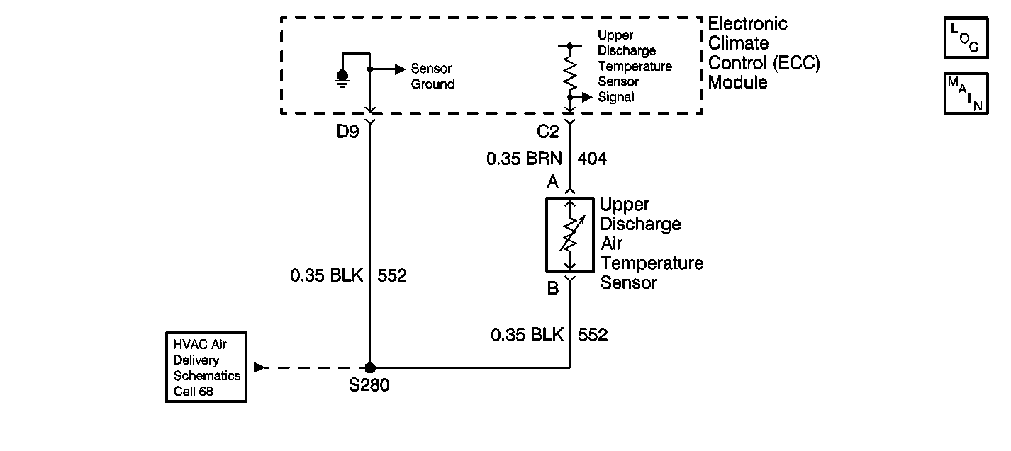
DTC B0175 Output Air Temp Sensor 1 Circuit Low Upper

Circuit Description
The upper discharge air temperature sensor is a thermistor used in order to control the signal voltage in the electronic climate control (ECC) module. The ECC module supplies a reference voltage (about 5 volts) on CKT 404 to the sensor. When the upper duct air temperature is cold, the thermistor resistance is high. Therefore, the ECC module will receive a high voltage input. If the upper duct air temperature is hot, the thermistor resistance is low. Therefore, the ECC module will receive a low signal voltage input. The upper discharge air temperature sensor is used in order to enhance the temperature control. Refer to Sensor Resistance Table .
Conditions for Setting the DTC
When the ignition is ON, the ECC module will detect DTC B0175 any time that CKT 404 is at or near zero voltage.
Action Taken When the DTC Sets
The ECC module will use a default value of 10 A/D counts until the fault is cleared.
Conditions for Clearing the MIL/DTC
This fault will clear as soon as the fault goes away or has been repaired. The system will then return to normal operation. History DTCs may only be cleared by removing and restoring B+ or by using the scan tool.
Diagnostic Aids
| • | The ECC module may set class 2 lost communication DTCs when the body control module (BCM) or the vehicle control module (VCM) is being reprogrammed. After reprogramming, inspect for DTCs in the ECC module. Clear any history U DTCs, then resume diagnostics. |
| • | Visually inspect the sensor connector and harness for corrosion and damage. The resistance value of the sensor must be 334-100,865 ohms. Refer to Sensor Resistance Table . If resistance is not within specifications, replace the sensor. |
Test Description
The numbers below refer to the step numbers on the diagnostic table.
-
This step measures the resistance of the upper discharge air temperature sensor.
-
This step inspects for a short to ground in CKT 404.
-
This step inspects for intermittents and tests for a malfunctioning ECC module.
-
This step repairs the short to ground in CKT 404.
-
This step replaces a defective upper discharge air temperature sensor.
-
This step replaces a defective ECC module.
Step | Action | Value(s) | Yes | No |
|---|---|---|---|---|
1 | Did you perform the Diagnostic System Check? | -- | Go to Step 2 | Go to Diagnostic System Check |
Is the resistance within the range specified in the table? | -- | Go to Step 3 | Go to Step 6 | |
Does the J 39200 DMM indicate less than the specified value? | 5 ohms | Go to Step 5 | Go to Step 4 | |
Does the DTC reset? | -- | Go to Step 7 | Go to Intermittents and Poor Connections Diagnosis in Wiring Systems | |
Repair the short to ground in CKT 404 (BRN). Is the repair complete? | -- | Go to Diagnostic System Check | -- | |
Replace the upper discharge air temperature sensor. Refer to Air Distributor Duct Replacement . Is the replacement complete? | -- | Go to Diagnostic System Check | -- | |
Replace the ECC module. Refer to Control Assembly Replacement . Is the replacement complete? | -- | Go to Diagnostic System Check | -- |
