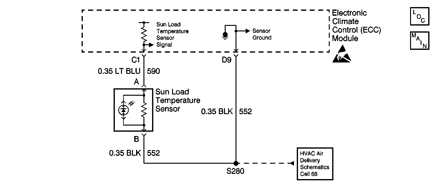
Circuit Description
The sun load temperature sensor is a reverse bias photo diode that measures sun load on the vehicle. The sensor is an input to the electronic climate control (ECC) module. High sensor impedance equates to full darkness. Low sensor impedance equates to bright sunlight.
Conditions for Setting the DTC
With the ignition ON, the ECC module will detect DTC B0185 any time that CKT 590 is at or near zero voltage.
Action Taken When the DTC Sets
The ECC module will use a default value of approximately 200 A/D counts until the fault is cleared.
Conditions for Clearing the MIL/DTC
This fault will clear as soon as the fault goes away or has been repaired. The system will then return to normal operation. History DTCs may only be cleared by removing and restoring B+ or by using the scan tool.
Diagnostic Aids
| • | The ECC module may set class 2 lost communication DTCs when the body control module (BCM) or the vehicle control module (VCM) is being reprogrammed. After reprogramming, inspect for DTCs in the ECC module. Clear any history U DTCs, then resume diagnostics. |
| • | Visually inspect the sensor connector and harness for corrosion and damage. |
Test Description
The numbers below refer to the step numbers on the diagnostic table.
-
This step inspects for a short to ground in CKT 590.
-
This step inspects for the display of sensor counts in the scan tool.
-
This step repairs the short to ground in CKT 590.
-
This step replaces a defective sun load temperature sensor.
-
This step inspects for a malfunctioning ECC module.
-
This step replaces a defective ECC module.
Step | Action | Value(s) | Yes | No |
|---|---|---|---|---|
1 | Did you perform the Diagnostic System Check? | -- | Go to Step 2 | Go to Diagnostic System Check |
Is the resistance less than the specified value? | 5 ohms | Go to Step 4 | Go to Step 3 | |
Are the counts equal to or less than the specified value? | 20 counts | Go to Step 5 | Go to Step 6 | |
Repair the short to ground in CKT 590 (LT BLU). Is the repair complete? | -- | Go to Diagnostic System Check | -- | |
Replace the sun load temperature sensor. Is the replacement complete? | -- | Go to Diagnostic System Check | -- | |
Does the DTC reset? | -- | Go to Step 7 | Go to Intermittents and Poor Connections Diagnosis in Wiring Systems | |
Replace the ECC module. Refer to Control Assembly Replacement . Is the replacement complete? | -- | Go to Diagnostic System Check | -- |
