Circuit Description
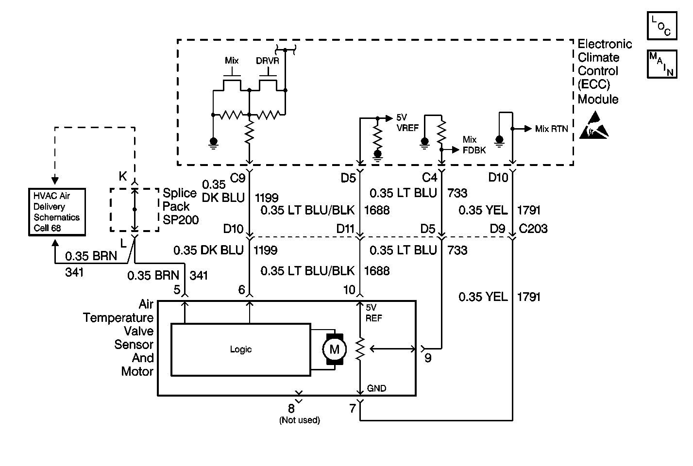
The air temperature valve sensor and motor is driven by the electronic climate control (ECC) module in order to operate the air temperature valve. The position of the air temperature valve is adjusted in order to maintain the verified air-outlet temperature. A feedback potentiometer is used in the flat-pack motor so that the ECC module will know the position of the air temperature valve. A low voltage at CKT 733 (about 1.0 volt) represents a cold air temperature valve position and a high voltage on CKT 733 (about 4.0 volts) represents a hot air temperature valve position. The ECC module drives the air temperature valve sensor and motor through CKT 1199 to the logic portion of the air temperature valve sensor and motor by applying 0 volts, 2.5 volts, and 5 volts through this circuit. Applying 5.0 volts on CKT 1199 to the logic portion of the air temperature valve sensor and motor will cause the air temperature valve to move to the full heat position. Applying 0.0 volts on CKT 1199 to the logic portion of the air temperature valve sensor and motor will cause the air temperature valve to move to the FULL COLD position. Applying approximately 2.5 volts on CKT 1199 will cause the air temperature valve sensor and motor to stop. Refer to Sensor Resistance Table .
Conditions for Setting the DTC
With the ignition ON, the ECC module will detect DTC B0415 anytime that CKT 733 is at or near 0.0 voltage.
Action Taken When the DTC Sets
The ECC module will drive the temperature valve to the FULL COLD position if the system is in one of the following modes:
| • | UPPER OUTLET |
| • | BI-LEVEL |
| • | AUTO UPPER OUTLET/BI-LEVEL MODE |
The ECC module will drive the temperature valve to the full heat position if the system is in one of the following modes:
| • | LOWER |
| • | DEFOG |
| • | DEFROST |
| • | AUTO LOWER |
Conditions for Clearing the MIL/DTC
DTC B0415 will clear as soon as the fault goes away or has been repaired. The system will then return to normal operation. History DTCs may only be cleared by removing and restoring B+ or by using the scan tool.
Diagnostic Aids
| • | The ECC module may set class 2 lost communication DTCs when the body control module (BCM) or the vehicle control module (VCM) is being reprogrammed. After reprogramming, inspect for DTCs in the ECC module. Clear any history U DTCs then resume diagnostics. |
| • | Visually inspect the air temperature valve sensor and motor and harness connector for loose or bent pins. If B+ has been removed from the ECC module and then restored for any reason, the ECC module system will (one time) drive the air temperature valve to FULL HOT and then to FULL COLD positions when B+ is restored. |
Test Description
The numbers below refer to the step numbers on the diagnostic table.
-
This step tests for voltage between terminal 9 and terminal 10 and the air temperature valve sensor motor.
-
This step repairs the air temperature valve sensor motor.
-
This step tests for voltage at terminal 10.
-
This step inspects for a short in CKT 733.
-
This step repairs a short in CKT 733.
-
This step replaces the ECC module.
-
This step inspects for a short in CKT 1688.
-
This step repairs a short in CKT 1688.
-
This step inspects the clearing of DTCs.
Step | Action | Value(s) | Yes | No |
|---|---|---|---|---|
1 | Did you perform the Diagnostic System Check? | -- | Go to Step 2 | Go to Diagnostic System Check |
Is the voltage measure the specified value? | 5 V | Go to Step 3 | Go to Step 4 | |
Replace the air temperature valve sensor and motor. Refer to Temperature Actuator Replacement . Is the replacement complete? | -- | Go to Diagnostic System Check | -- | |
Inspect the voltage reading at terminal 10. Is the voltage measured the specified value? | 5 V | Go to Step 5 | Go to Step 8 | |
Did you find a short to ground? | -- | Go to Step 6 | Go to Step 10 | |
Repair the short to ground in CKT 733. Is the repair complete? | -- | Go to Diagnostic System Check | -- | |
Replace the ECC module. Refer to Control Assembly Replacement . Is the replacement complete? | -- | Go to Diagnostic System Check | -- | |
Did you find a short to ground? | -- | Go to Step 9 | Go to Step 7 | |
Repair the short to ground in CKT 1688. Is the repair complete? | -- | Go to Diagnostic System Check | -- | |
Does the DTC reset? | -- | Go to Step 7 | Go to Diagnostic System Check |
