Tools Required
J 39400-A Halogen Leak Detector
Removal Procedure
- Disconnect the underhood lamp electrical connector, if equipped.
- Remove the hood. Refer to Hood Replacement in Body Front End.
- Remove the PCM. Refer to the appropriate procedure:
- Remove the coolant recovery tank. Refer to Coolant Recovery Reservoir Replacement in Engine Cooling.
- Disconnect the electrical connectors from the grille mounted lamps, if equipped.
- Remove the right front headlamp assembly. Refer to Front Bumper Impact Bar Replacement in Bumpers.
- Remove the front bumper. Refer to Front Bumper Impact Bar Replacement in Bumpers.
- Remove the right wheelhouse panel. Refer to Wheelhouse Panel Replacement in Body Front End.
- Disconnect the radio antenna cable.
- Disconnect the electrical connector for the horn.
- Remove the right fender. Refer to Front Fender Replacement in Body Front End.
- Remove the blower motor resistor. Refer to Blower Motor Resistor Replacement .
- Remove the accumulator. Refer to Air Conditioning Accumulator Replacement .
- Remove the evaporator tube. Refer to Evaporator Tube Replacement .
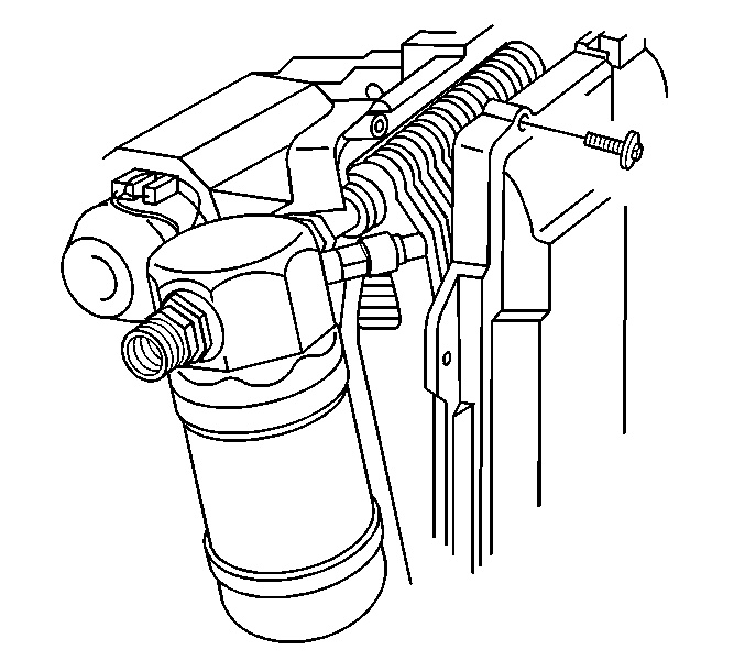
- Remove the evaporator and blower module heat shield mounting screws.
- Remove the evaporator and blower module heat shield.
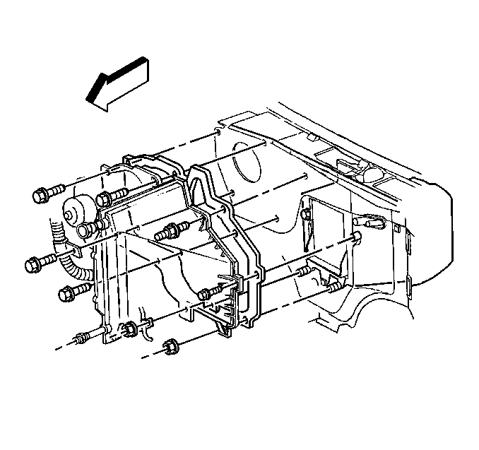
- Remove the evaporator and blower module mounting bolts and nuts.
- Remove the evaporator and blower module from the vehicle.
- Remove the 6 retaining screws holding the evaporator case section to the blower case section.
- Separate the evaporator case section from the blower case section.
- Remove the evaporator core from the blower case section.
- Inspect the seals and replace as necessary.
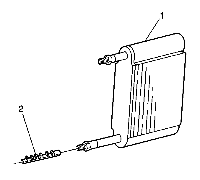
- Remove the expansion (orifice) tube (2) from the evaporator (1).
| • | Powertrain Control Module Replacement/Programming in Engine Controls-2.2L |
| • | VCM Replacement/Programming in Engine Controls-4.3L |
Important: Retain the evaporator and blower module heat shield mounting bracket for installation.


Installation Procedure
- Install the expansion (orifice) tube (2) to the evaporator (1).
- Install the evaporator core to the blower case section.
- Assemble the evaporator case section to the blower case section.
- Install the 6 retaining screws.
- Install the evaporator and blower module to the vehicle.
- Install the evaporator and blower module mounting fasteners.
- Install the evaporator and blower module heat shield .
- Install the evaporator and blower module heat shield mounting screws .
- Install the evaporator tube.
- Install the accumulator.
- Install the blower motor resistor. Refer to Blower Motor Resistor Replacement .
- Install the right fender. Refer to Front Fender Replacement in Body Front End.
- Connect the electrical connector for the horn.
- Install the radio antenna cable.
- Install the right wheelhouse panel. Refer to Wheelhouse Panel Replacement in Body Front End.
- Install the front bumper. Refer to Front Bumper Impact Bar Replacement in Body Front End.
- Install the right front headlamp assembly. Refer to Headlamp Replacement in Lighting Systems.
- Connect the electrical connectors to the grille mounted lamps.
- Install the coolant recovery tank. Refer to Coolant Recovery Reservoir Replacement in Engine Cooling.
- Install the PCM. Refer to the appropriate procedure:
- Install the hood. Refer to Hood Replacement in Body Front End.
- Connect the underhood lamp electrical connector.
- Evacuate and recharge the A/C system. Refer to Refrigerant Recovery and Recharging .
- Leak test the fittings components using theJ 39400-A .


Important: Ensure that the seal is in place between the 2 case sections.
Notice: Use the correct fastener in the correct location. Replacement fasteners must be the correct part number for that application. Fasteners requiring replacement or fasteners requiring the use of thread locking compound or sealant are identified in the service procedure. Do not use paints, lubricants, or corrosion inhibitors on fasteners or fastener joint surfaces unless specified. These coatings affect fastener torque and joint clamping force and may damage the fastener. Use the correct tightening sequence and specifications when installing fasteners in order to avoid damage to parts and systems.
Tighten
Tighten the screws to 1.9 N·m (17 lb in).
Important: Ensure that the evaporator and blower module to the cowl seal is in place.
Important: Install the evaporator and blower module heat shield mounting bracket with the evaporator and blower module mounting nuts .

Tighten
Tighten the bolts and the nuts to 4.5 N·m (40 lb in).
Tighten
Tighten the screws to 2.2N·m (19 lb in).
Refer to Evaporator Tube Replacement .
Refer to Air Conditioning Accumulator Replacement .
| • | Powertrain Control Module Replacement/Programming in Engine Controls - 2.2L |
| • | VCM Replacement/Programming in Engine Controls - 4.3L |
