Tie Rod Replacement RWD
Tools Required
| • | J 24319-B Steering
Linkage and Tie Rod Puller |
| • | J 29193 Steering
Linkage Installer (12 mm) |
| • | J 29194 Steering
Linkage Installer (14 mm) |
Removal Procedure
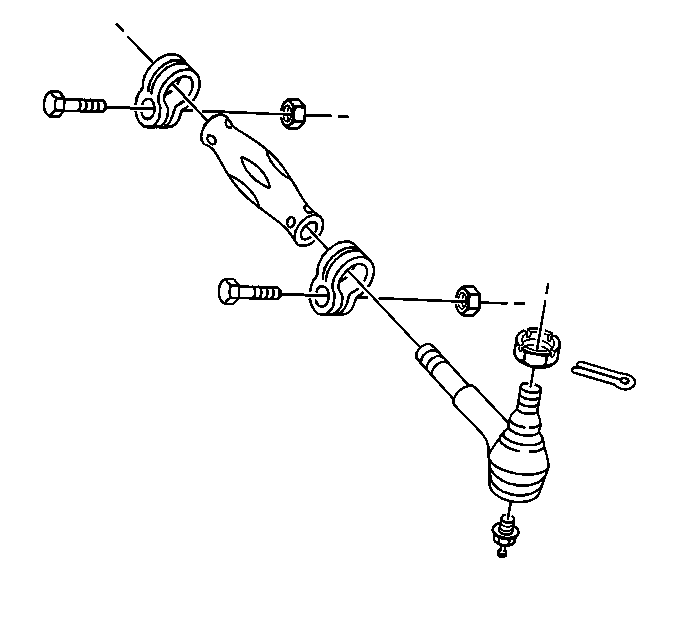
- Raise and suitably support
the vehicle with safety stands. Refer to
Lifting and Jacking the Vehicle
in General Information.
- Remove the cotter pin from outer tie rod ball stud nut.
- Remove the outer tie rod ball stud nut.
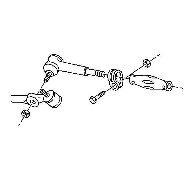
- Remove the inner tie rod
ball stud nut.
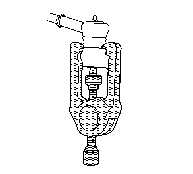
Notice: Do not attempt to disconnect a steering linkage joint by driving a wedge
between the joint and the attached part. Seal damage may result which will
cause premature failure of the joint.
Important: Use the proper tool in order to separate all tie rods and ball joints.
- Remove the outer tie rod ball stud from the steering knuckle using J 24319-B
.
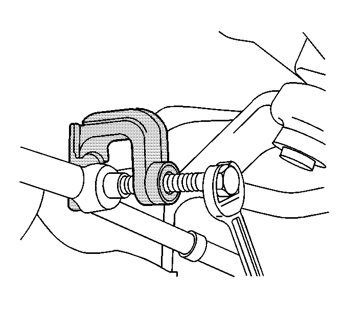
- Remove the inner tie rod
ball stud from the relay rod using J 6627-A
.
- Perform the following steps in order to remove the tie rod ends
from the adjuster tube:
| 7.1. | Loosen the clamp bolts. |
| 7.2. | Unscrew the assemblies. |
- Inspect for the following possible conditions:
| • | The tie rod ends for damage |
| • | The tie rod end seals for excessive wear |
| • | The tie rod threads for damage |
| • | The tie rod ends for damage |
| • | The ball stud threads for damage |
| • | The adjuster tube for bending |
| • | The adjuster tube for damaged threads |
- Clean the following components:
Installation Procedure
Important: If the tie rod ends were removed, lubricate the tie rod ends with chassis
lubricant.
- Connect the tie rod ends to the adjuster tube.
Ensure that the number of threads on both the inner and the outer tie
rod ends are equal within three threads.

- Install the inner tie
rod ball stud to the relay rod.
Ensure that the seal is on the stud.
Notice: Use the correct fastener in the correct location. Replacement fasteners
must be the correct part number for that application. Fasteners requiring
replacement or fasteners requiring the use of thread locking compound or sealant
are identified in the service procedure. Do not use paints, lubricants, or
corrosion inhibitors on fasteners or fastener joint surfaces unless specified.
These coatings affect fastener torque and joint clamping force and may damage
the fastener. Use the correct tightening sequence and specifications when
installing fasteners in order to avoid damage to parts and systems.
- Seat the taper using J 29193
or J 29194
.
Tighten
Tighten J 29193
or J 29194
to 54 N·m
(40 lb ft).
- Remove J 29193
or J 29194
from inner
tie rod ball stud.
- Install the new nut to the inner tie rod ball stud.
Tighten
Tighten the inner tie rod ball stud nut to the relay rod to 47 N·m
(35 lb ft).

- Connect the outer tie
rod ball stud to the steering knuckle.
Ensure that the seal is on the stud.
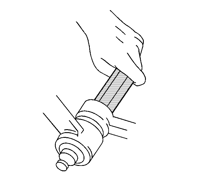
- Seat the taper using J 29193
or J 29194
.
Tighten
Tighten J 29193
or J 29194
to 54 N·m
(40 lb ft).
- Remove J 29193
or J 29194
from outer
tie rod ball stud.
- Install the nut to the outer tie rod ball stud.
Tighten
Tighten the outer tie rod ball stud nut to the steering knuckle to 53 N·m
(39 lb ft).
Important: Do not back the nut off in order to align the cotter pin hole. Advance
the nut in order to align the nut slot with the cotter pin hole.
- Install the new cotter pin to the outer tie rod stud nut.
- Spread the cotter pin ends.
- Lower the vehicle.
- Adjust the front toe. Refer to
Front Toe Adjustment
in Wheel Alignment.
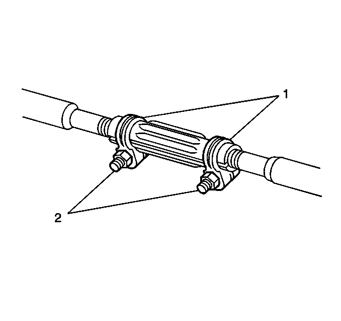
- Position the two clamps (2) between the locating dimples (1) at either
end of the adjuster tube.
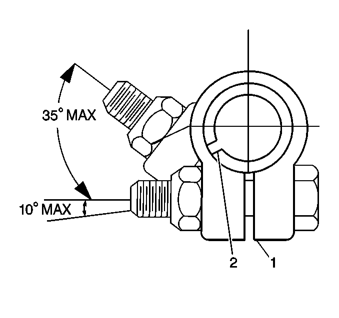
- The clamps must be positioned
within the correct angular travel, as shown.
- Ensure that the clamp slot (2) is not aligned with the adjuster
tube slot (1).
- Maintain the position of each tie rod end as the clamps are tightened
in order to ensure free movement of each joint.
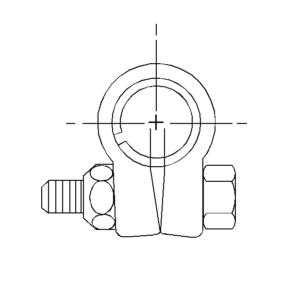
- When clamps are tightened
to specifications, the ends may touch.
- Install the adjuster tube clamp bolts.
Tighten
Tighten the adjuster tube clamp bolts to 21 N·m (16 lb ft).
Tie Rod Replacement 4WD
Tools Required
| • | J 24319-B Steering
Linkage and Tie Rod Puller |
| • | J 29193 Steering
Linkage Installer (12 mm) |
| • | J 29194 Steering
Linkage Installer (14 mm) |
Removal Procedure
- Raise and suitably support the vehicle with safety stands. Refer
to
Lifting and Jacking the Vehicle
in General Information.
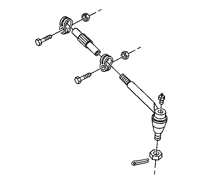
- Remove the cotter pin from outer tie rod ball stud nut.
- Remove the outer tie rod ball stud nut.
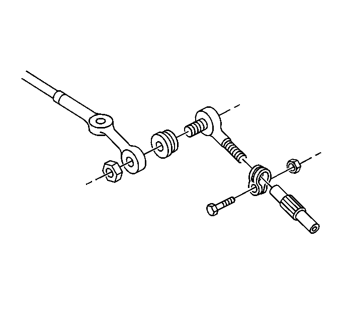
- Remove the inner tie rod ball stud nut.

Notice: Do not attempt to disconnect a steering linkage joint by driving a wedge
between the joint and the attached part. Seal damage may result which will
cause premature failure of the joint.
Important: Use the proper tool in order to separate all tie rods and ball joints.
- Remove the outer tie rod ball stud from the steering knuckle using J 24319-B
.
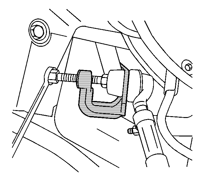
- Remove the inner tie rod
ball stud from the relay rod using J 6627-A
.

- Perform the following steps in order to remove the tie rod ends from
the adjuster tube:
| 7.1. | Loosen the clamp bolts. |
| 7.2. | Unscrew the assemblies. |
- Inspect for the following possible conditions:
| • | The tie rod ends for damage |
| • | The tie rod end seals for excessive wear |
| • | The tie rod threads for damage |
| • | The tie rod end for damage |
| • | The ball stud threads for damage |
| • | The adjuster tube for bending |
| • | The adjuster tube for damaged threads |
- Clean the following components:
Installation Procedure
Important:
| • | If the tie rod ends were removed, lubricate the tie rod ends with
chassis lubricant. |
| • | Ensure that the number of threads on both the inner and the outer
tie rod ends are equal within three threads. |
- Connect the tie rod ends to the adjuster tube.

- Install the inner tie rod ball stud to the relay rod.
Ensure that the seal is on the stud.
Notice: Use the correct fastener in the correct location. Replacement fasteners
must be the correct part number for that application. Fasteners requiring
replacement or fasteners requiring the use of thread locking compound or sealant
are identified in the service procedure. Do not use paints, lubricants, or
corrosion inhibitors on fasteners or fastener joint surfaces unless specified.
These coatings affect fastener torque and joint clamping force and may damage
the fastener. Use the correct tightening sequence and specifications when
installing fasteners in order to avoid damage to parts and systems.
- Seat the taper using J 29193
or J 29194
.
Tighten
Tighten J 29193
or J 29194
to 54 N·m
(40 lb ft).
- Remove J 29193
or J 29194
from the
inner tie rod ball stud.
- Install the new nut to the inner tie rod ball stud.
Tighten
Tighten the inner tie rod ball stud nut to 47 N·m (35 lb ft).

- Install the outer tie rod ball stud to the steering knuckle.
Ensure that the seal is on the stud.

- Seat the taper using J 29193
or J 29194
.
Tighten
Tighten J 29193
or J 29194
to 54 N·m
(40 lb ft).
- Remove J 29193
or J 29194
from the
outer tie rod ball stud.
- Install the nut to the outer tie rod ball stud.
Tighten
Tighten the outer tie rod ball stud nut to 53 N·m (39 lb ft).
Important: Do not back the nut off in order to align the cotter pin hole. Advance
the nut in order to align the nut slot with the cotter pin hole.
- Install the new cotter pin to outer tie rod nut.
- Spread the cotter pin ends.
- Lower the vehicle.
- Adjust the front toe. Refer to
Front Toe Adjustment
in Wheel Alignment.

- Position the two clamps (2) between the locating dimples (1) at either
end of the adjuster tube.

- The clamps must be positioned
within the correct angular travel, as shown.
- Ensure that the clamp slot (2) is not aligned with the adjuster
tube slot (1).
- Maintain the position of each tie rod end as the clamps are tightened
in order to ensure free movement of each joint.

- When clamps are tightened
to specifications, the ends may touch.
- Install the adjuster tube clamp bolts.
Tighten
Tighten the adjuster tube clamp bolts to 21 N·m (16 lb ft).


