Wheel Speed Sensor Replacement for GMC Truck Jimmy - 4WD 2001
Wheel Speed Sensor Replacement 4WD
Removal Procedure
- Raise the vehicle.
- Remove tire and wheel. Refer to Tire and Wheel Removal and Installation in Tires and Wheels.
- Remove brake caliper. Refer to Front Brake Caliper Replacement .
- Remove the hub and rotor. Refer to Front Brake Rotor Replacement .
- Remove wheel speed sensor mounting clip on the control arm.
- Remove wheel speed sensor mounting clip on the frame rail.
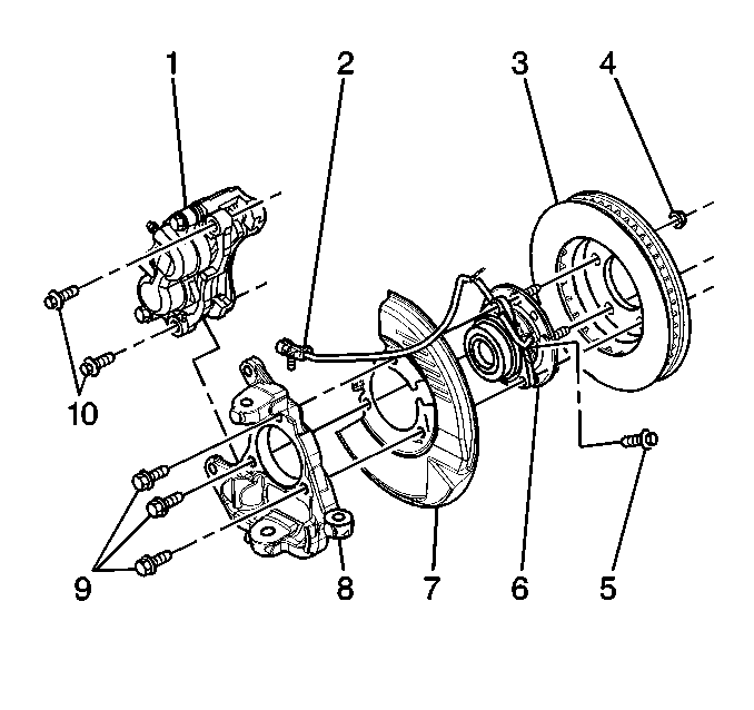
- Disconnect the wheel speed sensor electrical connector (2).
- Remove the sensor mounting screw (5).
- Remove wheel speed sensor from hub and bearing assembly.
NOTICE: Carefully remove the sensor by pulling it straight out of the bore. DO NOT use a screwdriver, or other device. Prying will cause the sensor body to break off in the bore.
NOTICE: Do not attempt to remove the stainless steel shim from the bearing assembly. The shim is permanently attached. If the shim is damaged or bent, replace the bearing assembly. Failure to comply will result in diminished sensor and ABS performance.
Important: The wheel speed sensor mounts into a bore that leads to the center of the sealed bearing. Use caution when cleaning or working around the bore. Do not contaminate the lubricant inside the sealed bearing. Failure to do so can lead to premature bearing failure.
Installation Procedure
- Install sensor into the hub and bearing assembly (6).
- Connect the wheel speed sensor electrical connector (2).
- Install wheel speed sensor mounting clip to the frame rail.
- Install the wheel speed sensor mounting clip to the control arm.
- Install the hub and rotor. Refer to Front Brake Rotor Replacement .
- Install brake caliper. Refer to Front Brake Caliper Replacement .
- Install tire and wheel. Refer to Tire and Wheel Removal and Installation in Tires and Wheels.
Notice: Use the correct fastener in the correct location. Replacement fasteners must be the correct part number for that application. Fasteners requiring replacement or fasteners requiring the use of thread locking compound or sealant are identified in the service procedure. Do not use paints, lubricants, or corrosion inhibitors on fasteners or fastener joint surfaces unless specified. These coatings affect fastener torque and joint clamping force and may damage the fastener. Use the correct tightening sequence and specifications when installing fasteners in order to avoid damage to parts and systems.
Important: The new speed sensor will have a new O-ring. Dispose of the old O-ring. Lubricate the new O-ring lightly with bearing grease prior to installation. You may also lubricate the sensor just above and below the new O-ring. DO NOT lubricate the bore.
Tighten
Tighten the sensor mounting screw (5) to 18 N·m (13 lb ft).
Important: The new sensor has new mounting clips already installed on the wire. DO NOT reuse the old clips.
Wheel Speed Sensor Replacement RWD
Removal Procedure
- Raise the vehicle.
- Remove tire and wheel. Refer to Tire and Wheel Removal and Installation in Tires and Wheels.
- Remove brake caliper. Refer to Front Brake Caliper Replacement .
- Remove the hub and rotor. Refer to Front Brake Rotor Replacement .
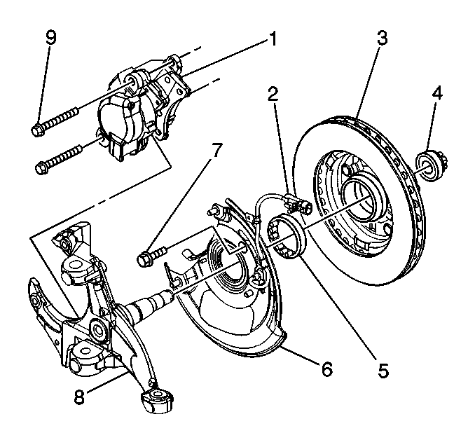
- Remove wheel speed sensor cable electrical connector (2).
- Remove 13 mm bolt and nut fastening the wheel speed sensor harness clip to the front side of the upper control arm.
- Remove clips from the wheel speed sensor wire. Save the clips for the sensor wire.
- Remove two 13 mm wheel speed sensor mounting bolts (7).
- Remove two 11 mm splash shield mounting bolts.
- Remove wheel speed sensor and splash shield assembly (6).
- Remove splash shield gasket.
- Clean gasket and knuckle surfaces thoroughly with a dry cloth.
Installation Procedure
- Install splash shield gasket.
- Install wheel speed sensor and splash shield assembly (6).
- Install two 11 mm splash shield mounting bolts.
- Install harness clips to the wheel speed sensor wire.
- Locate the clip directly centered over the white paint mark on the wheel speed sensor cable.
- Install harness clips and 13 mm fastening bolt and nut to the front side of the upper control arm
- Install the hub and rotor. Refer to Front Brake Rotor Replacement .
- Install brake caliper. Refer to Front Brake Caliper Replacement .
- Install tire and wheel. Refer to Tire and Wheel Removal and Installation in Tires and Wheels.
Notice: Use the correct fastener in the correct location. Replacement fasteners must be the correct part number for that application. Fasteners requiring replacement or fasteners requiring the use of thread locking compound or sealant are identified in the service procedure. Do not use paints, lubricants, or corrosion inhibitors on fasteners or fastener joint surfaces unless specified. These coatings affect fastener torque and joint clamping force and may damage the fastener. Use the correct tightening sequence and specifications when installing fasteners in order to avoid damage to parts and systems.
Tighten
| • | Tighten the splash shield mounting bolts to 16 N·m (12 lb ft) |
| • | Tighten the speed sensor mounting bolts (7) to 26 N·m (19 lb ft) |
