| Table 1: | Cellular Telephone Handset (Envoy) Connector C1 |
| Table 2: | Cellular Telephone Handset (Envoy) Connector C2 |
| Table 3: | Cellular Telephone Microphone (Envoy Only) |
| Table 4: | Microphone - Cellular Telephone |
| Table 5: | Speaker - Cellular Telephone |
| Table 6: | Vehicle Communication Unit (VCU-Transceiver) |
| Table 7: | Vehicle Interface Unit (VIU) - C1 |
| Table 8: | Vehicle Interface Unit (VIU) - C2 |
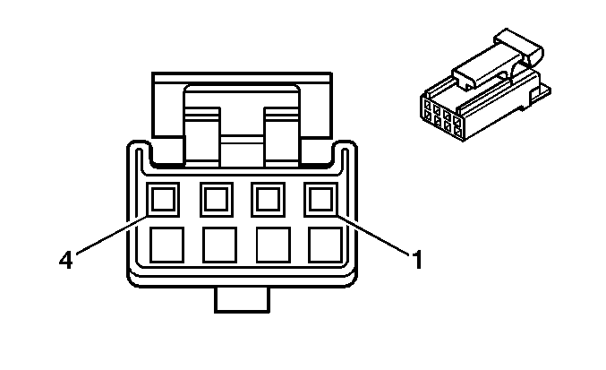
| |||||||
|---|---|---|---|---|---|---|---|
Connector Part Information |
| ||||||
Pin | Wire Color | Circuit No. | Function | ||||
1 | LT BLU | 1153 | Audio Handset Mouthpiece Signal | ||||
2 | DK BLU | 1154 | Audio Handset Earpiece Signal | ||||
3 | PNK | 1155 | Audio Handset Low Reference | ||||
4 | TAN | 1158 | Handset Fax Data Signal | ||||
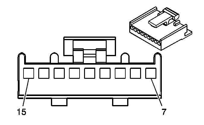
| |||||||
|---|---|---|---|---|---|---|---|
Connector Part Information |
| ||||||
Pin | Wire Color | Circuit No. | Function | ||||
7 | BRN | 1941 | Ignition 3 Voltage | ||||
8 | RED | 1266 | 8.5 Volt Reference | ||||
9 | PPL | 1156 | Handset Keypad Data Signal | ||||
10 | GRY/BLK | 1798 | Ground | ||||
11 | YEL | 1157 | Handset Display Data Signal | ||||
12-15 | -- | -- | Not Used | ||||
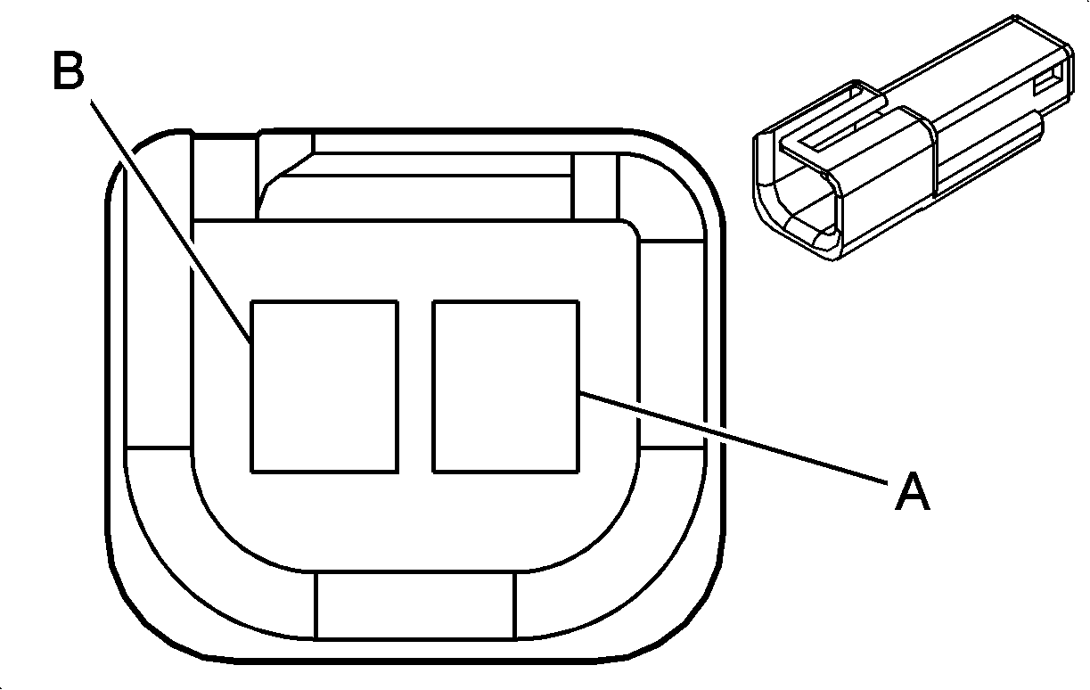
| |||||||
|---|---|---|---|---|---|---|---|
Connector Part Information |
| ||||||
Pin | Wire Color | Circuit No. | Function | ||||
A | BARE | 813 | Drain Wire | ||||
B | GRY | 655 | Cellular Telephone Microphone Signal | ||||
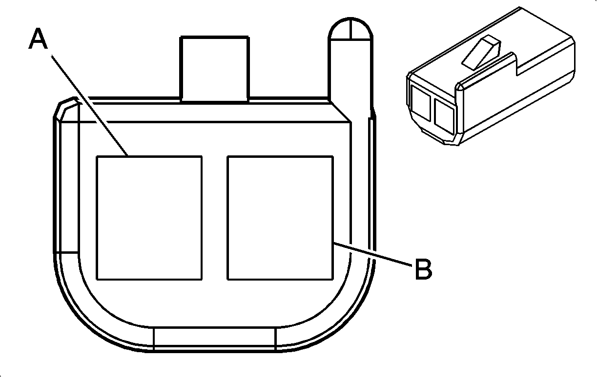
| |||||||
|---|---|---|---|---|---|---|---|
Connector Part Information |
| ||||||
Pin | Wire Color | Circuit No. | Function | ||||
A | BARE | 1705 | Drain Wire | ||||
B | GRY | 655 | Cellular Telephone Microphone Signal | ||||
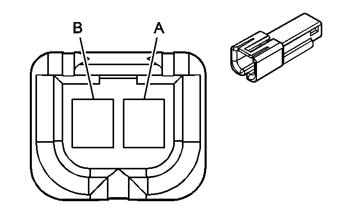
| |||||||
|---|---|---|---|---|---|---|---|
Connector Part Information |
| ||||||
Pin | Wire Color | Circuit No. | Function | ||||
A | PNK | 1159 | External Speaker Output | ||||
B | GRY | 1160 | External Speaker Output | ||||
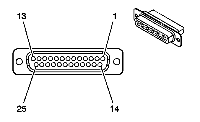
| |||||||
|---|---|---|---|---|---|---|---|
Connector Part Information |
| ||||||
Pin | Wire Color | Circuit No. | Function | ||||
1 | DK GRN/WHT | 2507 | Audio Transmit Signal | ||||
2 | -- | -- | Not Used | ||||
3 | GRY/BLK | 2520 | Transceiver Low Reference | ||||
4 | ORN | 2240 | Battery Positive | ||||
5 | PPL/WHT | 2513 | Ignition ON Signal | ||||
6 | BRN/WHT | 2506 | Audio Return Signal | ||||
7-10 | -- | -- | Not Used | ||||
11 | LT BLU/BLK | 2512 | OnStar Serial Data (+) | ||||
12 | DK BLU/WHT | 2511 | OnStar Serial Data (-) | ||||
13 | -- | -- | Not Used | ||||
14 | BARE | 1792 | Drain Wire | ||||
15 | GRY/BLK | 2508 | Microphone Signal | ||||
16-17 | -- | -- | Not Used | ||||
18 | TAN/BLK | 2510 | OnStar Serial Data Return | ||||
19-23 | -- | -- | Not Used | ||||
24 | BLK/WHT | 1235 | Audio Low Reference | ||||
25 | -- | -- | Not Used | ||||
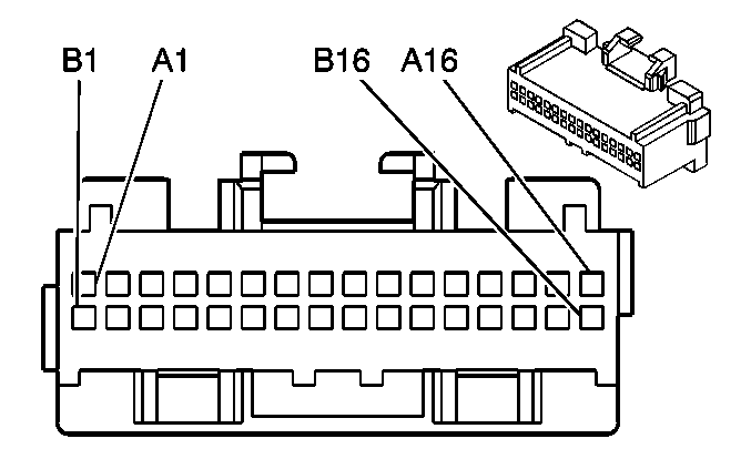
| |||||||
|---|---|---|---|---|---|---|---|
Connector Part Information |
| ||||||
Pin | Wire Color | Circuit No. | Function | ||||
A1 | -- | -- | Not Used | ||||
A2 | LT GRN/BLK | 1098 | Vehicle Communication Class 2 Serial Data | ||||
A3 | DK GRN | 835 | Entertainment and Comfort Serial Data | ||||
A4-A5 | -- | -- | Not Used | ||||
A6 | BLK/WHT | 372 | Remote Radio Audio Output (-) | ||||
A7 | DK GRN/WHT | 368 | Remote Radio Right Audio Signal | ||||
A8 | BRN/WHT | 367 | Remote Radio Left Audio Signal | ||||
A9 | BARE | 814 | Drain Wire | ||||
A10 | BLK/WHT | 1235 | Audio Low Reference | ||||
A11 | BRN/WHT | 2506 | Audio Return Signal | ||||
A12 | DK GRN/WHT | 2507 | Audio Transmit Signal | ||||
A13 | BARE | 1792 | Drain Wire | ||||
A14 | GRY/BLK | 2508 | Microphone Signal | ||||
A15 | BARE | 1782 | Drain Wire | ||||
A16 | ORN | 2540 | Battery Positive Voltage | ||||
B1-B8 | -- | -- | Not Used | ||||
B9 | GRY | 655 | Cellular Telephone Microphone Signal | ||||
B10 | BARE | 1705 | Drain Wire | ||||
B11 | TAN/BLK | 2510 | OnStar Serial Data Return | ||||
B12 | DK BLU/WHT | 2511 | OnStar Serial Data (-) | ||||
B13 | LT BLU/BLK | 2512 | OnStar Serial Data (+) | ||||
B14 | GRY/BLK | 2520 | Transceiver Low Reference | ||||
B15 | PPL/WHT | 2513 | Ignition ON Signal | ||||
B16 | -- | -- | Not Used | ||||
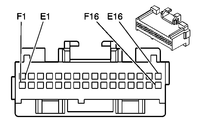
| |||||||
|---|---|---|---|---|---|---|---|
Connector Part Information |
| ||||||
Pin | Wire Color | Circuit No. | Function | ||||
E1 | BLK | 1450 | Ground | ||||
E2-E3 | -- | -- | Not Used | ||||
E4 | DK GRN/WHT | 2514 | Keypad Signal | ||||
E5 | YEL/BLK | 2516 | Keypad Green LED | ||||
E6 | LT GRN/BLK | 2515 | Keypad Supply Voltage | ||||
E7-E15 | -- | -- | Not Used | ||||
E16 | ORN | 640 | Battery Positive Voltage | ||||
F1 | BLK | 1450 | Ground | ||||
F2-F3 | -- | -- | Not Used | ||||
F4 | ORN/BLK | 2518 | Keypad Low Reference | ||||
F5 | -- | -- | Not Used | ||||
F6 | PNK | 39 | Ignition 1 Voltage | ||||
F7-F8 | -- | -- | Not Used | ||||
F9 |
BRN/WHT | 2517 | Keypad Red LED Signal | ||||
F10 | -- | -- | Not Used | ||||
F11 | DK GRN | 1301 | RAP Relay Coil Supply Voltage | ||||
F12-F15 | -- | -- | Not Used | ||||
F16 | ORN | 640 | Battery Positive Voltage | ||||
