Side Door Lock Pillar Garnish Molding Replacement CF5
Removal Procedure
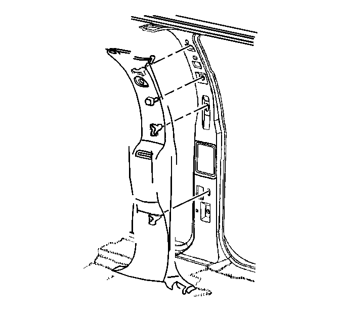
- Remove the front and rear door sill trim plates. Refer to Door Sill Plate Replacement .
- Remove the upper and lower front seat belt anchor bolts.
- Remove the front side door lock pillar garnish molding from the vehicle. Feed the seat belt through the garnish molding.

Installation Procedure
- Install the front side door lock pillar garnish molding to the vehicle. Feed the seat belt through the garnish molding.
- Install the upper and the lower front seat belt anchor bolts.
- Install the front and the rear door sill trim plates. Refer to Door Sill Plate Replacement .

Notice: Use the correct fastener in the correct location. Replacement fasteners must be the correct part number for that application. Fasteners requiring replacement or fasteners requiring the use of thread locking compound or sealant are identified in the service procedure. Do not use paints, lubricants, or corrosion inhibitors on fasteners or fastener joint surfaces unless specified. These coatings affect fastener torque and joint clamping force and may damage the fastener. Use the correct tightening sequence and specifications when installing fasteners in order to avoid damage to parts and systems.
Tighten
Tighten the screws to 70 N·m (52 lb ft).
Side Door Lock Pillar Garnish Molding Replacement ZRX/Xtreme
Removal Procedure
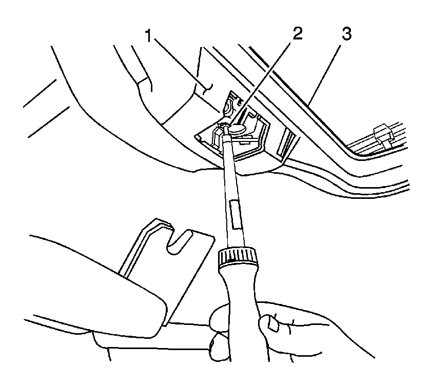
- Remove the motor/actuator service cover.
- Remove the motor actuator cover screw (2).
- Disengage the switch from the motor/actuator cover.
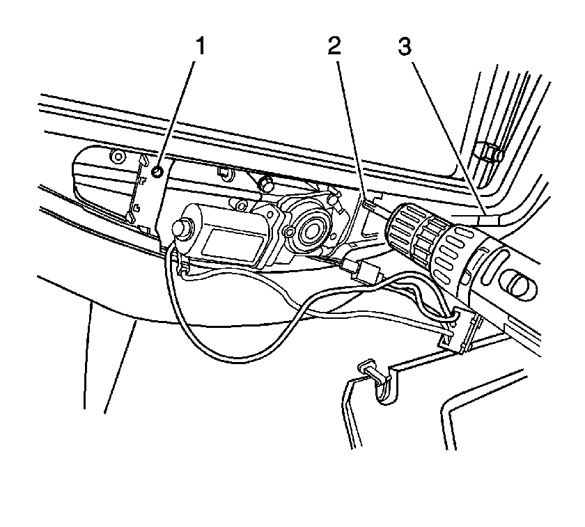
- Remove the motor/actuator cover.
- Remove the two short screws (1, 2), one on each side of the motor/actuator.
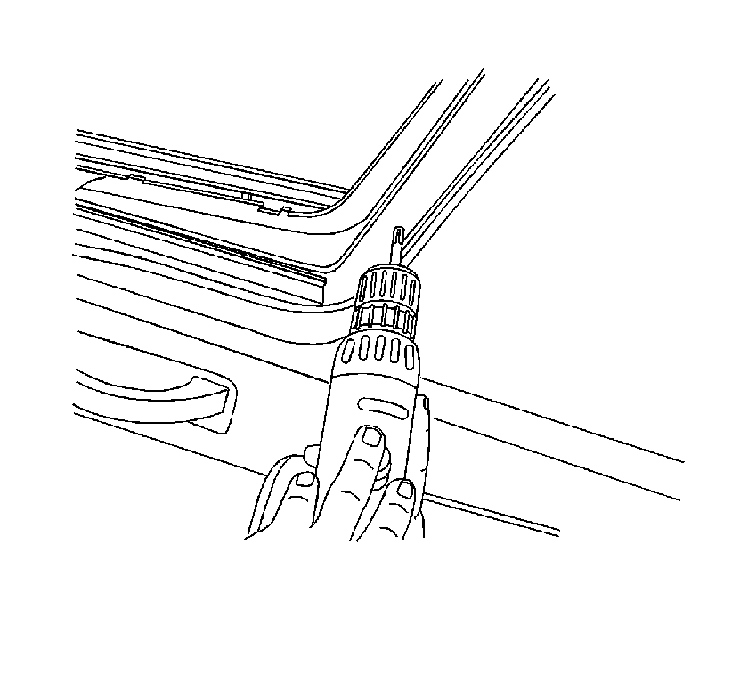
- Using a small flat-bladed tool, gently pry the eight screw covers from the interior garnish molding.
- Remove the eight screws securing the garnish molding to the lower frame assembly.
- Remove the garnish molding from the vehicle.

Important: The interior garnish molding uses two different size screws. The two forward screws under the motor/actuator cover are short. The remaining eight screws are long.


Installation Procedure
- Position the garnish to the headliner.
- Loosely install one forward and one rearward screw to the garnish molding in order to hold the garnish molding into position.
- Install the remaining screws.
- Install the switch to the motor/actuator cover.
- Install the motor/actuator cover (1) to the garnish molding.
- Install the screw (2).
- Connect the electrical connector.
- Install the motor/actuator service cover.

Notice: Refer to Fastener Notice in the Preface section.
The two short screws are positioned on each side of the motor/actuator.
Tighten
Tighten the screws to 1.5 N·m (13 lb in).

Tighten
Tighten the screw to 4 N·m (35 lb in).
