SERVICE MANUAL UPDATE-SEC. 7B3 BORG-WARNER T5 MANUAL TRANS.

SUBJECT: BORG-WARNER T5 MANUAL TRANSMISSION UNIT REPAIR (REVISED INFORMATION)
MODELS: 1993 S MODELS WITH BORG-WARNER T5 MANUAL TRANSMISSION (RPO MW1)
This information replaces the information found under BORG-WARNER T5 MANUAL TRANSMISSION in SECTION 7B3 of the 1993 Light Duty Truck Unit Repair Manual.
Beginning with the 1993 model year, the Borg-Warner T5 Manual Transmissions were built with needle bearings under the mainshaft gears.
Update your 1993 Light Duty Truck Unit Repair Manual with the following pages.
SECTION 7B3
BORG-WARNER T5 MANUAL TRANSMISSION
NOTICE: When fasteners are removed, always reinstall them at the same location from which they were removed. If a fastener needs to be replaced, use the correct part number fastener for that application. If the correct part number fastener is not available, a fastener of equal size and strength (or stronger) may be used. Fasteners that are not reused, and those requiring thread locking compound will be called out The correct torque value must be used when installing fasteners that require it. If the above conditions are not followed, parts or system damage could result.
CONTENTS
SUBJECT PAGE ------- ---- General Description ............................................. 7B3-1 Precautions ..................................................... 7B3-2 Unit Disassembly ................................................ 7B3-3 Transmission Disassembly ........................................ 7B3-3 Mainshaft Disassembly ........................................... 7B3-3 Drive Gear Disassembly .......................................... 7B3-8 Cleaning and Inspection ......................................... 7B3-8 Transmission Case ............................................... 7B3-8 Bearing Rollers and Spacers ..................................... 7B3-9 Front and Rear Bearings ......................................... 7B3-9 Synchronizer Blocker Rings ...................................... 7B3-9 Synchronizer Keys and Springs ................................... 7B3-10 Extension Housing Oil Seal and Bushing Replacement .............. 7B3-10 Drive Gear Bearing Retainer Oil Seal ............................ 7B3-11 Transmission Cover .............................................. 7B3-11 Front Countershaft Bearing ...................................... 7B3-12 Unit Assembly ................................................... 7B3-14 Drive Gear Assembly ............................................. 7B3-14 Mainshaft Assembly .............................................. 7B3-14 Transmission Assembly, .......................................... 7B3-14 Specifications .................................................. 7B3-17 Fastener Tightening Specifications .............................. 7B3-17 Lubrication Specifications ...................................... 7B3-17 Special Tools ................................................... 7B3-18
GENERAL DESCRIPTION
The 77-mm 5-speed is a constant mesh transmission, synchronized in all speeds except reverse.
The main components are:
1. Main drive gear.
o An integral shaft is splined to engage with the clutch-driven plate.
o The gear drives the countershaft.
o A tapered bearing supports the shaft in the case.
2. Countershaft.
o The countershaft is one unit for constant rotation with the drive gear.
o Bearings support the countershaft in the case.
o Thrust washers limit the play of the countershaft.
o An extra gear is mounted to the countershaft for 5th speed.
3. Mainshaft.
o The drive gears rotate freely on the mainshaft and are in constant mesh with the countershaft.
o Key-type synchronizers engage the gears.
o The first and second synchronizer hub is machined in place.
o A tapered bearing supports the mainshaft in the rear of the case.
o Roller bearings support the mainshaft independently in the drive gear.
o The drive gear and mainshaft are engaged by a synchronizer for direct drive in fourth gear.
o Thrust washers limit the play of the mainshaft.
4. Reverse idler gear.
o The idler gear drives the mainshaft in reverse.
o The idler gear is supported on its own shaft.
5. Shift lever.
o The shift lever is mounted on the extension housing.
o The shift lever moves the shafts which are mounted in the transmission top cover and case.
o Shift forks mounted on shafts move the synchronizers to engage the gears.
o A pin-type interlock blocks the other shafts when one is moved.
PRECAUTIONS
Certain precautions should be followed when repairing the transmission. unless proper care is taken, the components may be damaged.
o Repair of a transmission should be done in a clean work area. The outside of the case should be clean to keep dirt out of the transmission. On transmissions with a standard gearshift lever, install the lever before cleaning the outside of the transmission.
o During transmission repair, all the parts should be cleaned in cleaning solvent and then air dried. Wiping cloths or rags should not be used to dry the parts as lint may get on the parts and cause trouble later. All the parts, except those being worked on, should be kept covered with clean paper.
UNIT DISASSEMBLY
TRANSMISSION DISASSEMBLY
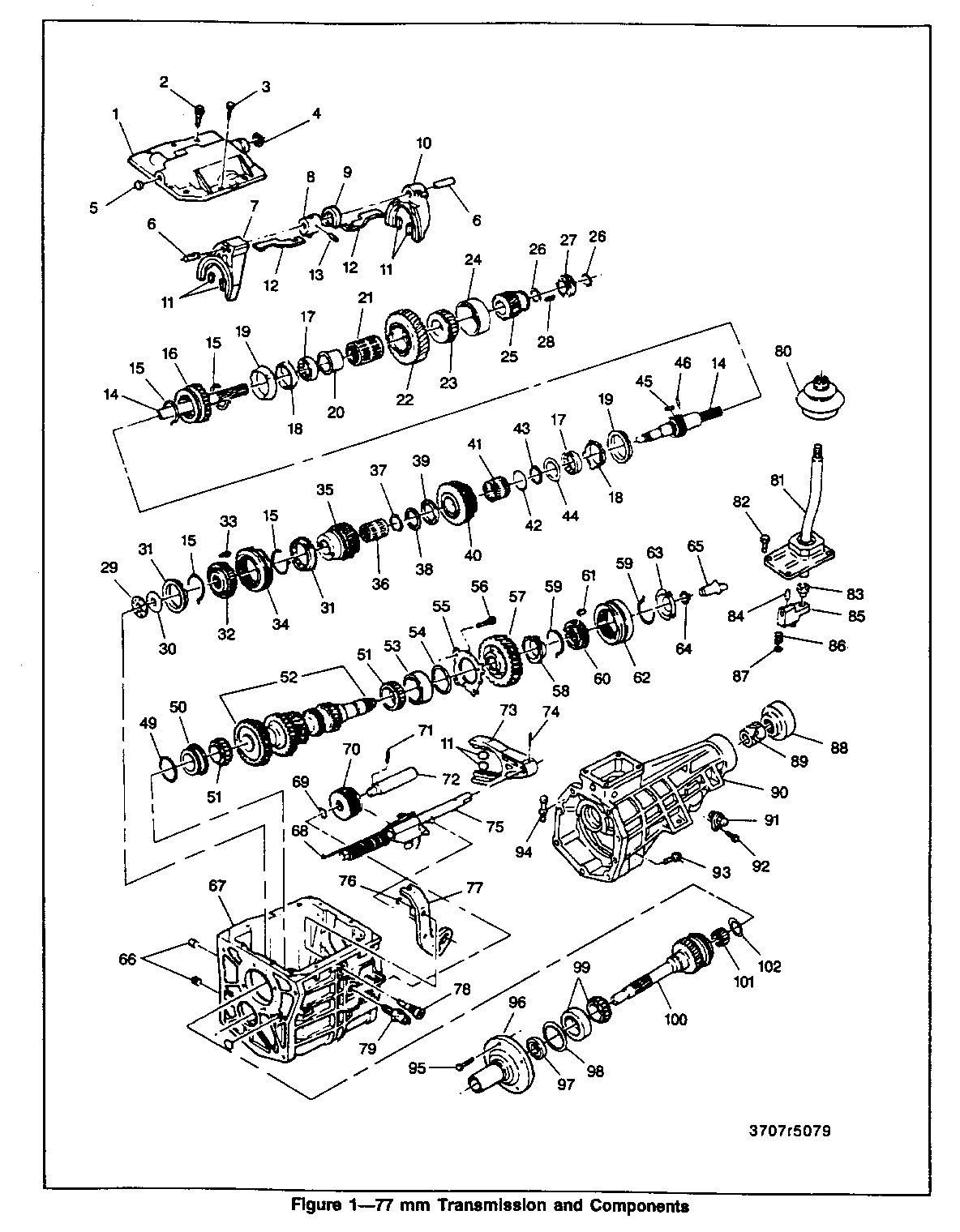
Remove or Disconnect (Figures 1 and 2)
Tools Required:
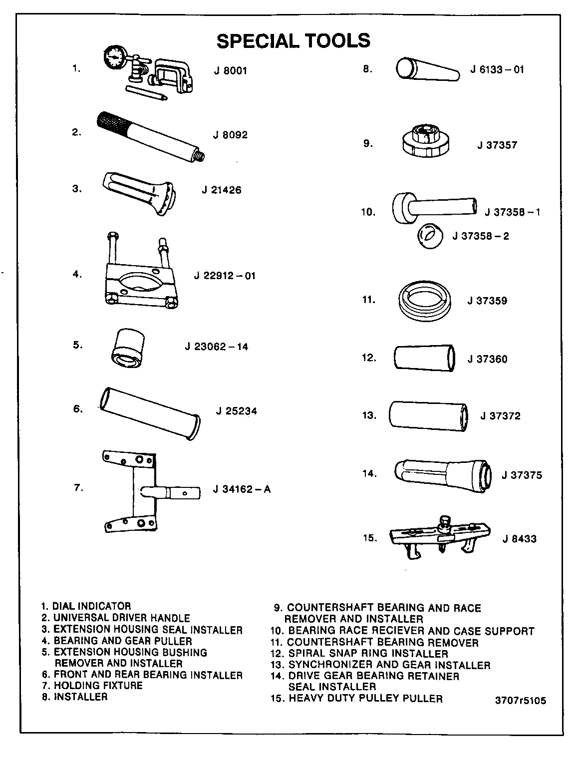
J 22912-01 Bearing and Gear Puller J 37359 Countershaft Bearing Remover o Remove drain bolt and drain the lubricant.
NOTICE: Removal of offset lever in position other than neutral (centered) may result in driving the roll pin into the detent plate without releasing the lever, making further disassembly extremely difficult.
o Position offset lever in neutral gate (centered).
1. Control lever (81).
o Boot and the dust cover.
2. Pin (84) from the offset lever (85) (figure 3).
3. Extension housing (90) to transmission case bolts (93).
4. Extension housing (90) and the offset lever (85).
Important
o The offset lever is engaged into the extension housing and cannot be removed when the extension housing is mounted to the transmission.
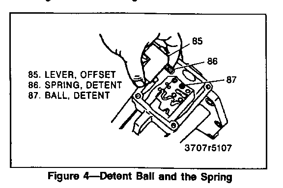
5. Detent ball (87) and the spring (86) from the offset lever (figure 4).
6. Pin from extension housing or the offset lever.
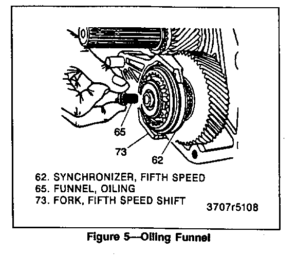
7. Oiling funnel (65) from rear of countershaft (52) (figure 5).
8. Bolts (3) attaching transmission cover (1) and shift fork assembly to the case (67).
Important
o Two of the cover mounting bolts are alignment bolts. Note the positions that they were removed from for reassembly.
9. Cover (1) from the case (67).
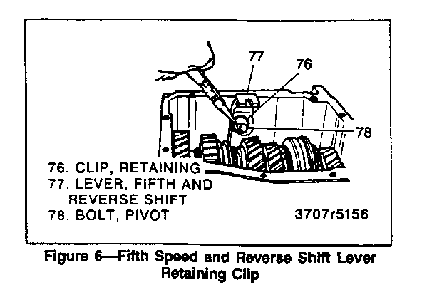
10. Reverse lever spring clip (76), pivot bolt (78), and shift lever (77) (figure 6).
11. Backup lamp switch (79).
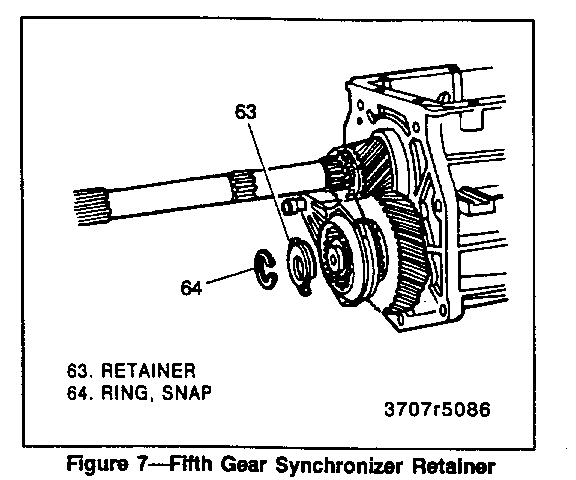
12. Fifth gear synchronizer snap ring (64) and retainer (63) from the rear of the countershaft (52) (figure 7).
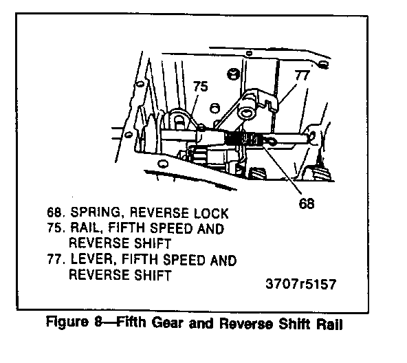
13. Reverse lock spring (68) from front of transmission case by unhooking it (figure 8).
14. Fifth gear (57), synchronizer (62), shift fork (73), and shift rail (75) as an assembly.
o If necessary, rotate rail to disengage it from reverse lever assembly
15. Speedometer gear (27) and retaining clip (28).
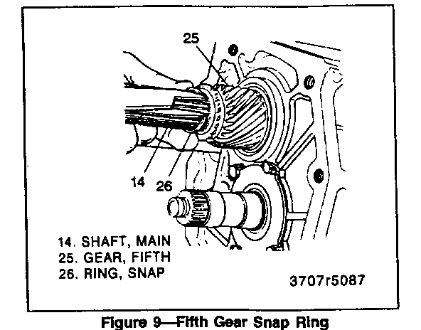
16. Snap ring (26) from the mainshaft (14) (figure 9).
o Mark the front bearing retainer and the case for alignment.
17. Front bearing retainer bolts (95).
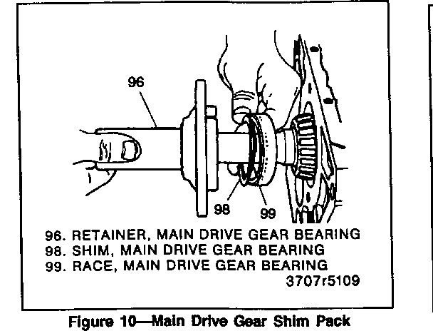
18. Front bearing retainer (96).
19. Front bearing race (99) and the shim pack (98) (figure 10).
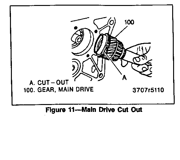
20. Main drive gear (100).
o Turn the gear so the cutout is toward the countershaft (figure 11).
o Be careful not to drop the 15 roller bearings, thrust bearing, or race from the rear of the drive gear.
21. Fourth gear blocker ring (31) from third/fourth synchronizer.
22. Mainshaft rear bearing race (24).
o If the race sticks, it is probably misaligned in the case bore. To free the race, work the shaft back and forth.
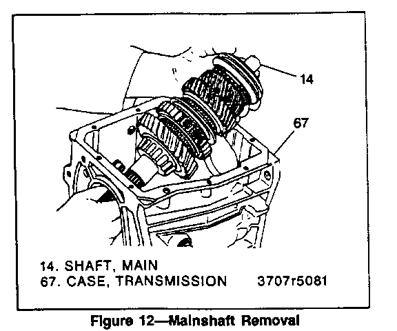
23. Mainshaft (14) (figure 12).
o Tilt mainshaft upward and remove assembly from the transmission case.
24. Reverse fork assembly from the transmission case.
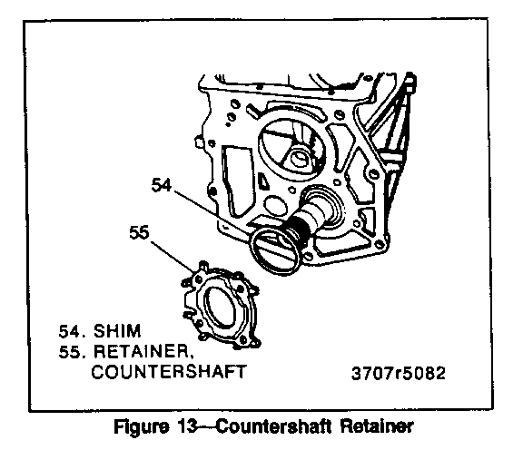
25. Countershaft retainer (55) and shims (54) (figure 13).
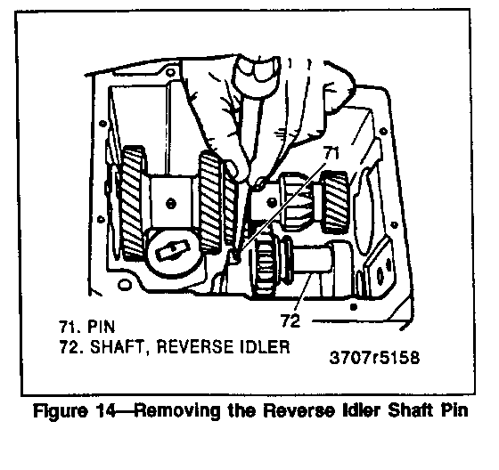
26. Roll pin (71) from the forward end of the reverse idler shaft (72) (figure 14).
27. Reverse idler shaft (72), rubber 0-ring (69), and gear (70) from the transmission case (67).
28. Rear countershaft bearing race (53).
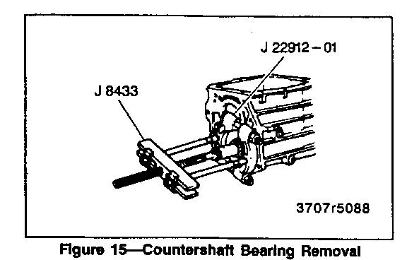
29. Countershaft bearing (51) using J 8433 with J 22912-01 and J 37359 (figure 15).
Important
o Note the direction the bearing faces.
30. Countershaft (52).
o Move the countershaft assembly rearward, tilt it upward, and remove from case.
MAINSHAFT DISASSEMBLY
Disassemble (Figures 1 and 2)
Tool Required:
J 22912-01 Bearing and Gear Puller
1. Thrust bearing (29) and the race (30) from the front of the main shaft (14).
o Scribe a reference mark on the third-fourth synchronizer hub and sleeve for reassembly
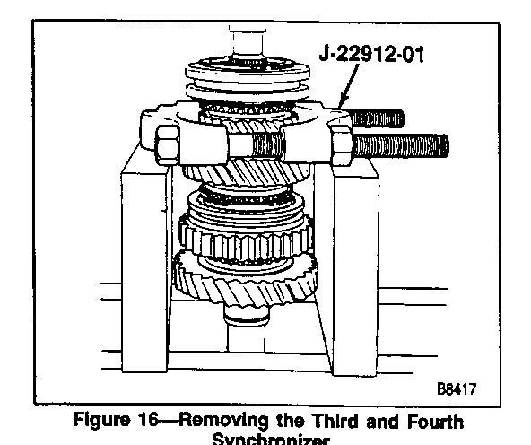
2. Third-fourth synchronizer, third blocker ring (31), sleeve (34), hub (32), and third gear (35) as an assembly from the mainshaft using J 22912-01 and a press (figure 16).
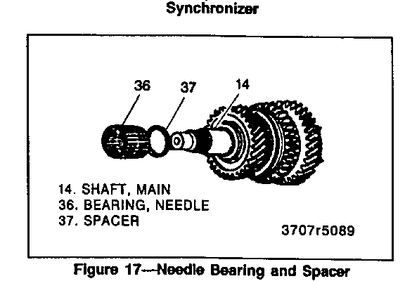
3. Needle bearing assembly (36) and spacer (37) (figure 17).
4. Second gear snap ring (38) and thrust washer (39).
5. Second gear (40), spacer (42), and needle bearing (41).
6. Spiral snap ring (43).
7. Thrust washer (44).
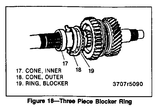
8. Three-piece second gear blocker ring assembly (figure 18).
o Scribe a reference mark on first-second synchronizer hub and sleeve for reassembly.
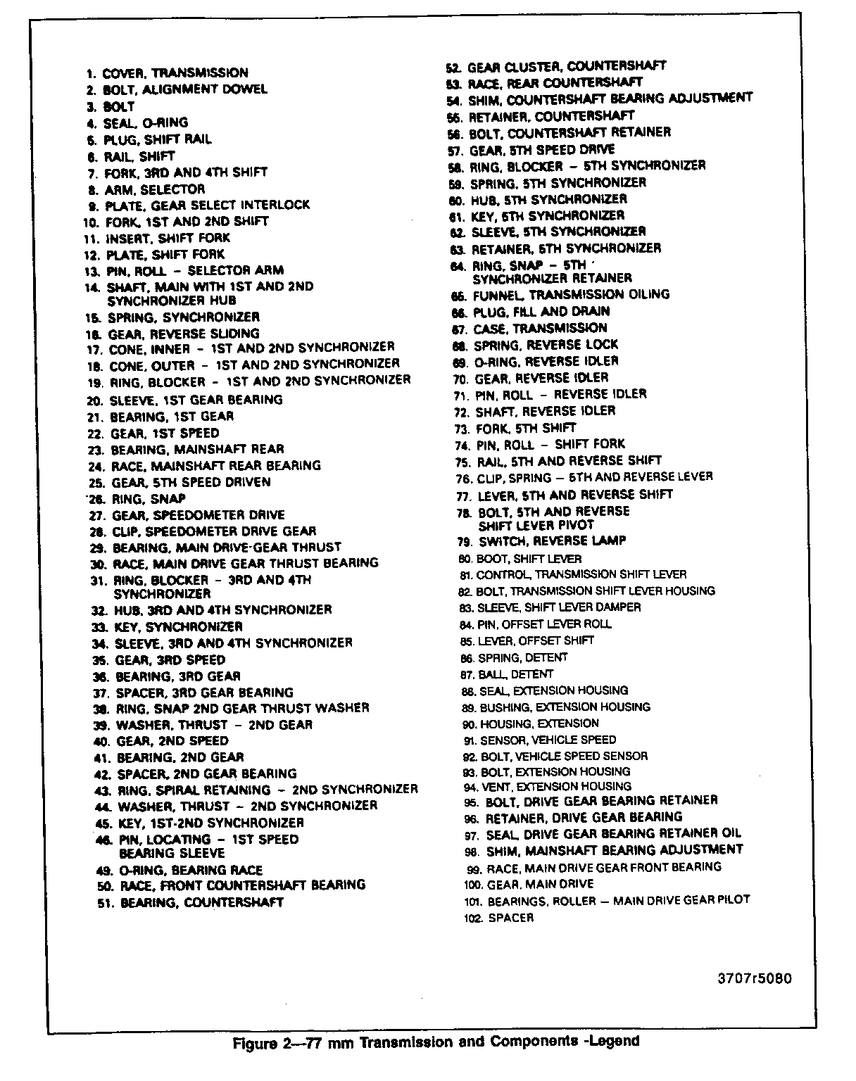
1. COVER, TRANSMISSION 2. BOLT, ALIGNMENT DOWEL 3. BOLT 4. SEAL, 0 - RING 5. PLUG, SHIFT RAIL 6. RAIL, SHIFT 7. FORK, 3RD AND 4TH SHIFT 8. ARM, SELECTOR 9. PLATE, GEAR SELECT INTERLOCK 10. FORK, 1 ST AND AND 2ND SHIFT 11. INSERT, SHIFT FORK 12. PLATE, SHIFT FORK 13. PIN, ROLL - SELECTOR ARM 14. SHAFT, MAIN WITH 1ST AND 2ND SYNCHRONIZER HUB 15. SPRING, SYNCHRONIZER 16. GEAR, REVERSE SLIDING 17. CONE, INNER - 1ST AND 2ND SYNCHRONIZER 18. CONE, OUTER - 1ST AND 2ND SYNCHRONIZER 19. RING, BLOCKER - 1ST AND 2ND SYNCHRONIZER 20. SLEEVE, 1ST GEAR BEARING 21. BEARING, IST GEAR 22. GEAR, 1ST SPEED 23. BEARING, MAINSHAFT REAR 24. RACE, MAINSHAFT REAR BEARING 25. GEAR, 5TH SPEED DRIVEN 26. RING, SNAP 27. GEAR, SPEEDOMETER DRIVE 28. CLIP, SPEEDOMETER DRIVE GEAR 29. BEARING, MAIN DRIVE - GEAR THRUST 30. RACE, MAIN DRIVE GEAR THRUST BEARING 31. RING, BLOCKER - 3RD AND 4TH SYNCHRONIZER 32. HUB, 3RD AND 4TH SYNCHRONIZER 33. KEY, SYNCHRONIZER 34. SLEEVE, 3RD AND 4TH SYNCHRONIZER 35. GEAR, 3RD SPEED 36. BEARING, 3RD GEAR 37. SPACER, 3RD GEAR BEARING 38. RING, SNAP 2ND GEAR THRUST WASHER 39. WASHER, THRUST - 2ND GEAR 40. GEAR, 2ND SPEED 41. BEARING, 2ND GEAR 42. SPACER, 2ND GEAR BEARING 43. RING, SPIRAL RETAINING - 2ND SYNCHRONIZER 44. WASHER, THRUST - 2ND SYNCHRONIZER 45. KEY, 1 ST - 2ND SYNCHRONIZER 46. PIN, LOCATING - 1ST SPEED BEARING SLEEVE 49. 0 - RING, BEARING RACE 50. RACE, FRONT COUNTERSHAFT BEARING 51. BEARING, COUNTERSHAFT 52. GEAR CLUSTER, COUNTERSHAFT 53. RACE, REAR COUNTERSHAFT 54. SHIM, COUNTERSHAFT BEARING ADJUSTMENT 55. RETAINER, COUNTERSHAFT 56. BOLT, COUNTERSHAFT RETAINER 57. GEAR, 5TH SPEED DRIVE 58. RING, BLOCKER - 5TH SYNCHRONIZER 59. SPRING, 5TH SYNCHRONIZER 60. HUB, 5TH SYNCHRONIZER 61. KEY, 5TH SYNCHRONIZER 62. SLEEVE, 5TH SYNCHRONIZER 63. RETAINER, 5TH SYNCHRONIZER 64. RING, SNAP - 5TH SYNCHRONIZER RETAINER 65. FUNNEL, TRANSMISSION OIUNG 66. PLUG, FILL AND DRAIN 67. CASE, TRANSMISSION 68. SPRING, REVERSE LOCK 69. 0 - RING, REVERSE IDLER 70. GEAR, REVERSE IDLER 71. PIN, ROLL - REVERSE IDLER 72. SHAFT, REVERSE IDLER 73. FORK, 5TH SHIFT 74. PIN, ROLL - SHIFT FORK 75. RAIL, 5TH AND REVERSE SHIFT 76. CUP, SPRING - 5TH AND REVERSE LEVER 77. LEVER, 5TH AND REVERSE SHIFT 78. BOLT, 5TH AND REVERSE SHIFT LEVER PIVOT 79. SWITCH, REVERSE LAMP 80. BOOT. SHIFT LEVER 81. CONTROL, TRANSMISSION SHIFT LEVER 82. BOLT, TRANSMISSION SHIFT LEVER HOUSING 83. SLEEVE, SHIFT LEVER DAMPER 84. PIN, OFFSET LEVER ROH 85. LEVER, OFFSET SHIFT 86. SPRING, DETENT 87. BALL, DETENT 88. SEAL, EXTENSION HOUSING 89. BUSHING, EXTENSION HOUSING 90. HOUSING, EXTENSION 91. SENSOR, VEHICLE SPEED 92. BOLT, VEHICLE SPEED SENSOR 93. BOLT, EXTENSION HOUSING 94. VENT, EXTENSION HOUSING 95. BOLT, DRIVE GEAR BEARING RETAINER 96. RETAINER, DRIVE GEAR BEARING 97. SEAL, DRIVE GEAR BEARING RETAINER OIL 98. SHIM, MAINSHAFT BEARING ADJUSTMENT 99. RACE, MAIN DRIVE GEAR FRONT BEARING 100. GEAR, MAIN DRIVE 101. BEARINGS, ROLLER - MAIN DRIVE GEAR PILOT 102. SPACER
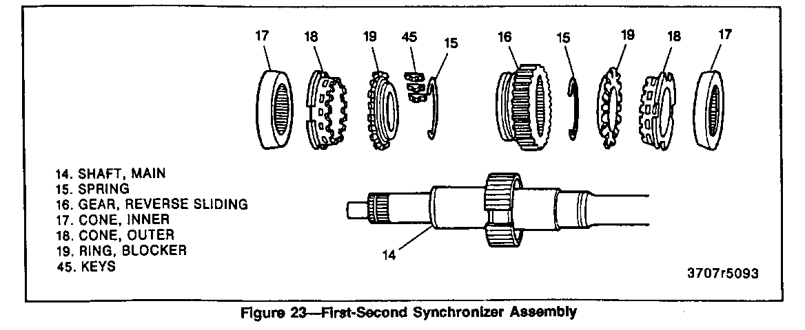
9. First-second synchronizer spring (15) and keys (45) from first-reverse sliding gear.
10. Sleeve (16) from mainshaft hub.
IMPORTANT
o Do not attempt to remove the first-second-reverse hub from the mainshaft. The hub and shaft are permanently assembled and machined as a matched set.
11. Fifth gear using J 22912-01 and a press.
12. Mainshaft rear bearing assembly (23 and 24).
13. First gear (22).
14. Needle bearing (21) and sleeve (20).
15. Locating pin (46).
16. Three-piece first gear blocker ring assembly.
DRIVE GEAR DISASSEMBLY
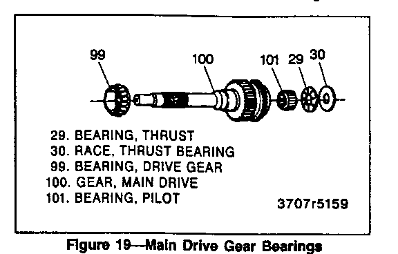
Disassemble (Figure 19)
Tool Required:
J 22912-01 Bearing and Gear Puller
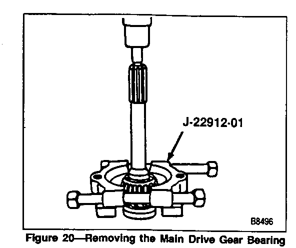
1. Bearing race (30). 2. Thrust bearing (29). 3. Roller bearings (101) from cavity of drive gear. 4. Bearing (99) from the drive gear using J 22912-01 and a press (figure 20).
Clean
o All parts in a suitable solvent. Do not spin the bearings dry.
Inspect
1. Gear teeth and shaft pilot for wear.
CLEANING AND INSPECTION
TRANSMISSION CASE
Clean
1. Transmission case thoroughly inside and outside with appropriate solvent.
2. Magnetic disk at the bottom of the transmission case.
Inspect
1. Case for cracks.
2. Front and rear faces of the transmission case for burrs, and if present, dress them off with a fine mill file.
BEARING ROLLERS AND SPACERS
Inspect
o Drive gear bearing rollers for chips, cracks, or excessive wear and replace if necessary.
o Reverse idler shaft for wear and damage.
o Spacers for wear.
FRONT AND REAR BEARINGS
Clean
1. Front and rear bearings thoroughly with appropriate solvent.
2. Blow out bearings with compressed air.
o Do not allow the bearings to spin. Turn them slowly by hand. Spinning bearings may damage the race and rollers.
3. Lubricate bearings with Dexron@ IIE or equivalent transmission fluid.
Inspect
o Bearings for roughness by slowly turning race by hand.
SYNCHRONIZER BLOCKER RINGS
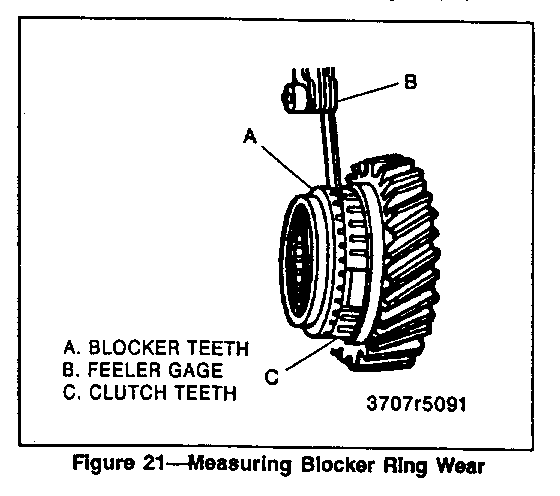
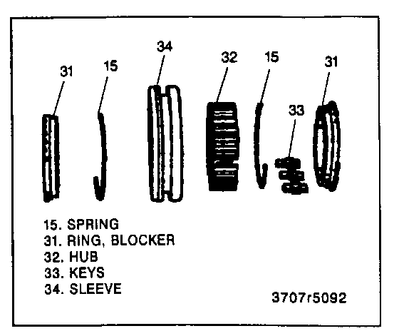
The first-second synchronizer outer cone and the third-fourth blocker ring are lined with friction material and cannot be checked visually for wear. Replacement is necessary when the gap between blocker teeth and adjacent clutch teeth is significantly less than specified.
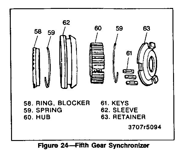
Fifth gear blocker ring is brass and can be checked visually for wear and damage.
Important
o Make certain the blocker rings are correctly identified before assembly. The first-second synchronizer blocker ring does not have friction material. The third-fourth synchronizer blocker ring has friction material. Assembling one in place of the other will result in serious damage to the transmission.
Inspect
o Fifth-gear blocker ring for wear and damage.
Third-Forth Blocker Rings
Assemble (Figures 21 and 22)
1. Third-gear blocker ring (31) to third gear (35) with twisting motion to fully seat.
2. Fourth-gear blocker ring (31) to drive gear (100) with twisting motion to fully seat.
Measure
o Gap between vertical faces of blocker teeth and clutch teeth. Nominal gap is 0.88 - 1.50 mm (0.035 - 0.059 inch) for new blocker rings.
First-Second Blocker Rings
Assemble (Figures 21 and 23)
1. Three-piece first-gear blocker ring assembly using a twisting motion to fully seat.
2. Three-piece first-gear blocker ring assembly with needle bearing (21) and bearing sleeve (20) to first gear (22).
3. Three-piece second gear blocker ring assembly using a twisting motion to fully seat.
4. Three-piece second gear blocker ring assembly with thrust washer (44) to second gear (40).
Measure
o Gap between vertical faces of blocker teeth and clutch teeth. Nominal gap is 0.81 - 1.40 mm (0.032 - 0.055 inch) for new blocker ring assemblies.
SYNCHRONIZER KEYS AND SPRINGS
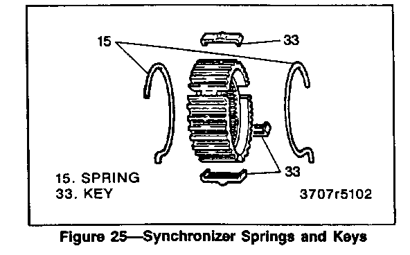
Important (Figures 22 through 25)
o The synchronizer hubs and sliding sleeves are a selected assembly and should be kept together as originally assembled. The keys and springs maybe replaced if worn or broken.
Remove or Disconnect
1. Keys and springs.
o Mark hub and sleeve for reassembly.
o Push the sliding sleeve from the hub. The keys will fall free and the springs may be easily removed.
Install or Connect
1. Keys and springs.
o Place a blocker ring on side of the hub and sleeve and install keys and retain with a spring.
o Place blocker ring on opposite side of the hub and sleeve and install remaining spring.
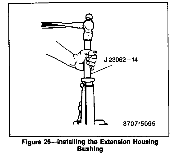
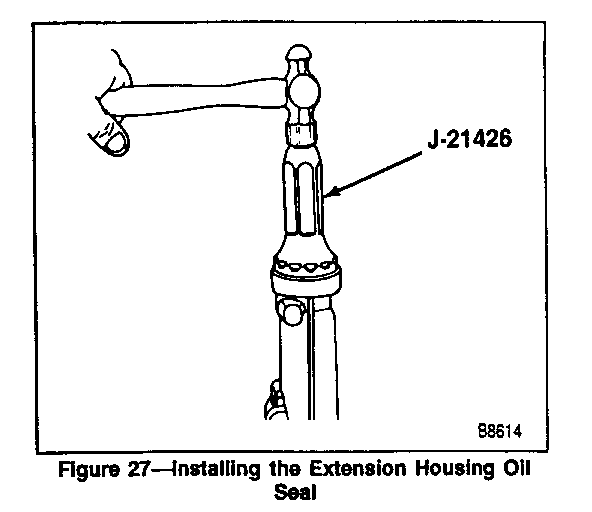
EXTENSION HOUSING OIL SEAL AND BUSHING REPLACEMENT
Remove or Disconnect (Figure 26)
Tool Required:
J 8092 Driver Handle J 23062-14 Extension Housing Bushing Remover and Installer
1. Seal (88).
2. Sealing compound from the flange of the extension housing.
3. Bushing (89) if it is worn or damaged, using J 8092 and J 23062-14.
Inspect
1. Extension for scoring, wear or cracks, especially at the flange . Install or Connect (Figures 26 and 27)
Tools Required:
J 8092 Driver Handle J 21426 Extension Housing Oil Seal Installer J 23062-14 Extension Housing Bushing
Remover and Installer
1. New bushing (89) if needed, using J 8092 and J 23062-14 (figure 26).
o Coat the bushing with transmission oil.
o Drive the bushing into the extension.
2. Locking compound on the outside of a new seal (88).
3. New seal (88) using J 21426 (figure 27).
o Lubricate inside diameter of seal with transmission oil.
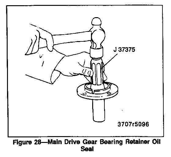
DRIVE GEAR BEARING RETAINER OIL SEAL
Remove or Disconnect (Figure 28)
1. Seal (97).
2. Sealing compound from flange of retainer (95).
Inspect
1. Retainer nose for scoring, wear, or cracks, especially at the flange.
2. Replace the retainer if it is worn or damaged.
Install or Connect (Figure 28)
Tool Required:
o J 37375 Bearing Retainer Seal Installer
o New seal (97) using J 37375.
o Lubricate the inside diameter of the seal with transmission oil.
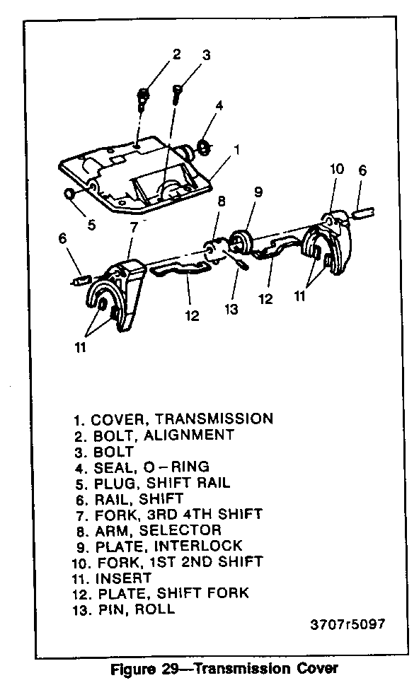
TRANSMISSION COVER
Disassemble (Figure 29)
o The shift rail and shift fork plates must be in the neutral position (centered).
1. Turn the shift rail (6) until the selector arm (8) is disengaged from the fork plates (12).
2. Drive the retaining pin (13) out of the selector arm (8).
3. Remove the shift rail (6), shift forks (7 and 10), shift fork plates (12), selector arm (8), interlock plate (9), and roll pin.
4. Pry the transmission cover to extension housing oil seal (4) out.
5. Remove the inserts (11) and shift fork plates from the forks.
o Note the position of inserts and plates for reassembly.
Clean
o All metal parts in solvent and air dry.
Inspect
1. Shift forks.
o For damage or bends. o For worn inserts.
2. Shift rail.
o For damage and bends. o For worn or damaged plates. o For smooth fit in the cover.
3. Transmission cover.
o For cracks and warping. o For smooth shift rail fit. o Shaft plug for damage or leaks.
Assemble (Figure 29)
o Coat the shift rail and the cover bores lightly with transmission assembly grease.
1. Install a new shift rail plug (5), if needed.
o Coat the outside of the plug with sealing compound.
2. Fit the inserts (11) and the fork plates (12) into the shift forks.
3. First and second (largest) shift fork (10).
o Fit the shift rail into the cover rear bore.
o Hold the shift fork in the cover with the fork off set to the rear.
o Push the shift rail through the fork.
4. Selector arm (8) and the interlock plate (9).
o Hold the selector arm and the interlock plate in the cover with the widest part of the plate away from the cover.
o The shift arm retaining pin hole must be away from the cover and to the rear.
o Push the shift fork through the arm.
5. Third and fourth shift fork (7).
o Hold the shift fork in the cover with fork offset to the rear.
o The fork plate must be under the first and second shift fork plate.
o Push the shift rail through the fork, into the cover front bore.
6. Turn the shift rail until the front fork plate is away from the cover and parallel to it.
7. Drive a new retaining pin (13) into the selector arm (8) and the shift rail (6).
o Be sure the arm and shaft pin holes are aligned
o The retaining pin must be flush with the selector arm.
8. Install a new oil seal (4).
o Coat the seal with transmission oil.
FRONT COUNTERSHAFT BEARING
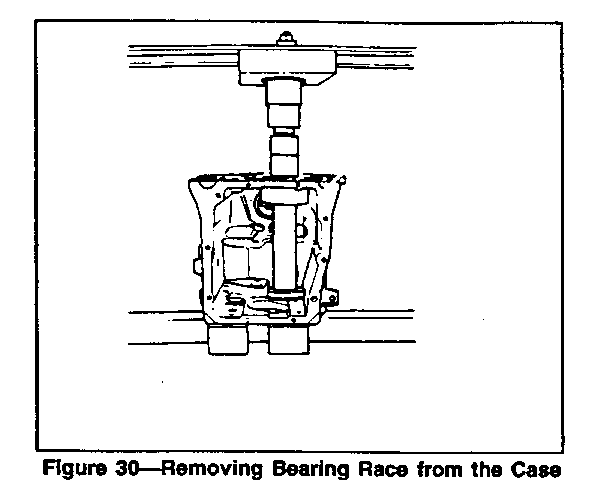
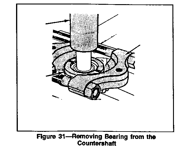
Remove or Disconnect (Figures 1, 2, 30, and 31)
Tools Required:
J 37358-1, -2 Bearing Race Receiver and Case
Support
J 22912-01 Bearing and Gear Puller
J 37359 Countershaft Bearing Remover
J 8092 Universal Driver Handle
Important
o Failure to support the case properly will result in permanent distortion of the case during bearing race removal.
1. Countershaft front bearing race (50) and 0-ring (49) from the transmission case using J 37358-1 with J 37358-2 with a press (figure 30).
o Remove the front countershaft bearing race only if it is worn or damaged.
2. Countershaft front bearing (51) from the countershaft (52) using J 22912-01 with J 37359, J 8092 and a press (figure 31).
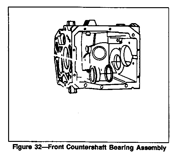
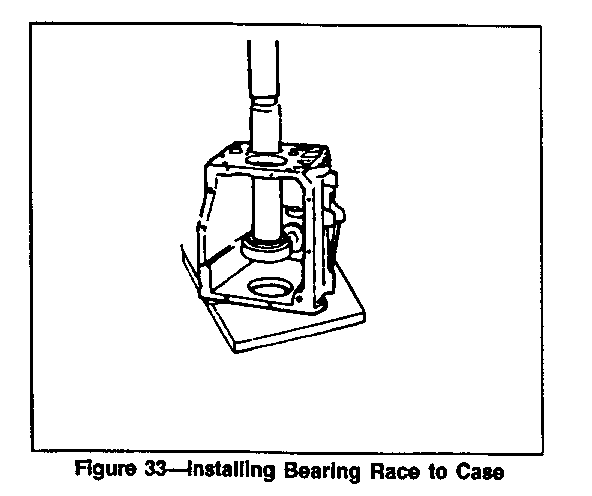
Install or Connect (Figures 1, 2, 32, and 33)
Tools Required:
J 37357 Countershaft Bearing and Race
Remover and Installer
J 22912-01 Bearing and Gear Puller J 8092 Universal Driver Handle
1. Countershaft front bearing (51) onto the countershaft (52) using J 37357 with J 22912-01, J 8092, and a press.
2. New 0-ring (49) onto the the countershaft front bearing race (50) (figure 32).
o Lubricate the 0-ring.
3. Countershaft front bearing race (50) into the transmission case (67) using J 37357 with J 8092 and a press (figure 33).
o Lightly tap the race into its bore until the 0-ring is compressed.
o Use a press to install the race until its shoulder rests on the inside of the case.
UNIT ASSEMBLY
Use new seals, gaskets, and thread sealer on all bolt threads when assembling the transmission. Tighten all bolts to specified torque.
Lubricate all assemblies as they are installed in the transmission using Dexron IIE automatic transmission fluid oil or equivalent.
DRIVE GEAR ASSEMBLY
Assemble (Figure 19)
Tools Required:
J 22912-01 Bearing and Gear Puller J 6133-01 Installer
1. Bearing (99) onto the drive gear (100) using J 22912-01 with J 6133-01 and a press.
o Coat roller bearings and drive gear bearing bore with lightweight grease.
2. Roller bearings (101) into the bore of the drive gear.
3. Thrust bearing (29) and race (30) into the drive gear.
MAINSHAFT ASSEMBLY
Assemble (Figures 1 and 2)
Tool Required:
J 25234 Front and Rear Bearing Installer J 37360 Spiral Snap Ring Installer J 37372 Synchronizer and Gear Installer
Important
o If replacing first-second or third-fourth synchronizer blocker rings, soak new blocker ring assemblies for 10 minutes in Dexron IIE or equivalent before assembly on mainshaft.
o Coat mainshaft and gear bores with transmission lubricant.
1. First-second synchronizer sleeve (16) on mainshaft hub.
o Align marks made during disassembly
Important
o Use care in synchronizer spring placement. If synchronizer is assembled with improper spring placement, hard shifting will result.
2. First-second synchronizer keys (45) and springs (15).
o Engage tang end of each spring in the same synchronizer key, but position open end of springs opposite of each other.
3. Three-piece first gear blocker ring assembly.
4. Locating pin (46) into the main shaft (14).
5. Sleeve (20) and needle bearing (21) into mainshaft, aligning notch in sleeve with locating pin.
6. First gear (22).
o Align slots in first gear with tabs on blocker ring assembly.
7. Rear mainshaft bearing (23) with taper facing rear of shaft.
8. Fifth gear (25) onto mainshaft (14) using J 25234 and a press.
o Lubricate fifth-gear splines with petroleum jelly.
o Carefully align the mainshaft and gear splines. If splines are improperly aligned, damage could occur when the gear is pressed onto the mainshaft.
9. Fifth gear snap ring.
10. Three-piece second gear blocker ring assembly and thrust washer (44).
11. Spiral snap ring (43) using J 37360.
12. Second gear spacer (42), needle bearing (41), and gear (40).
o Align slots in second gear with tabs on blocker ring assembly.
13. Second gear thrust washer (39) and snap ring (38).
14. Third gear spacer (37) and needle bearing assembly (36).
o Make sure the bearing spacer is not trapped between the gear face and snap ring. The spacer runs inside the gear bore.
15. Third-fourth synchronizer, third blocker ring (31), sleeve (34), hub (32), and third gear (35) as an assembly using J 37372 and a press.
16. Thrust bearing (29) and race (30) to front front end of mainshaft.
Important
o Before pressing components together, make sure the synchronizer hub faces the short end of the mainshaft. Hold third gear against the synchronizer to maintain blocker ring alignment with keys.
TRANSMISSION ASSEMBLY
Install or Connect (Figures 1 and 2)
NOTICE: For steps 5, 17, 20, 23, 29, 30, and 32, refer to "Notice" on page 7B3-1.
Tools Required:
J 37357 Countershaft Bearing and Race
Remover and Installer
J 8092 Universal Driver Handle J 37372 Synchronizer and Gear Installer J 8001 Dial Indicator
1. Countershaft (52) into case (67).
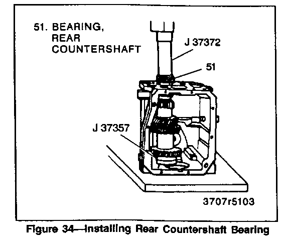
2. Rear countershaft bearing (51) to countershaft using J 37372 and a press (figure 34).
o Support the countershaft with J 37357.
Important
o Failure to properly support the countershaft may result in permanent distortion of the case during installation.
3. Rear countershaft bearing race (53).
4. Reverse idler gear (70) and the shaft (72).
o Hold the gear in the case with the shift lever groove to the rear.
o Install the reverse idler shaft from the rear.
o Install a new retaining pin (71).
5. Countershaft retainer (55) to transmission housing without shims.
Tighten
o Countershaft retainer bolts to 20 N-m (15 lbs. ft).
Measure
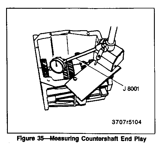
o Countershaft end play using dial indicator J 8001 (figure 35).
o Remove retainer and install shim(s) as necessary to provide proper end play. Zero end play with no preload is ideal, but up to 0.10 mm (0.004 inch) end play is allowable. Do not preload bearing with shim(s) larger than original end play measurement.
o Reinstall retainer (55) and bolts (56).
Tighten
o Retainer bolts (56) to 20 N-m (15 lbs. ft.).
o Bend tabs over the four attaching bolts.
6. Reverse shift fork in the case.
7. Mainshaft (14) into the transmission case.
8. Rear mainshaft bearing race (24).
9. Drive drive gear in case (100).
o Make sure rollers, thrust bearing, and washer are in place.
o Be sure to engage the third-fourth synchronizer sleeve and blocker ring.
10. Front bearing race (99) in the front bearing retainer (96).
o Do not install shims in front bearing retainer at this time.
11. Temporarily install front bearing retainer (96).
o Be sure to align the marks made during disassembly.
12. Fifth gear (57) on countershaft.
o Slide shift rail and fifth gear shift fork assembly into case.
o Align reverse shift fork and slide rail (75) through fork.
o Position lever return spring in case with long end of spring to the rear, and slide rail through the spring (68).
13. Blocker ring (58) and fifth gear synchronizer (62) in fifth gear shift fork (73).
o Slide fork rail assembly and synchronizer into position.
14. Fifth gear synchronizer retainer (63) and snap ring (64) (figure 8).
15. Oiling funnel (65) into rear of countershaft (figure 5).
16. Fifth gear and reverse shift lever (77) in the case (figure 6).
o Make sure reverse shift fork pin and fifth-gear shift rail pin are engaged with shift lever.
17. Fifth gear and reverse lever pivot bolt (78) and retaining clip (76).
o Coat pivot bolt threads with pipe sealant GM P/N 1052080 or equivalent.
Tighten
o Pivot bolt (76) to 27 N.m (20 lbs. ft.).
18. Backup lamp switch (79).
o Coat threads with pipe thread sealant GM P/N 1052080 or equivalent.
19. Transmission cover (1).
A. Move the shift forks and the synchronizers to the neutral positions.
B. Apply a 3 mm (1/8-inch) bead of RTV sealant GM P/N 12345739, or equivalent, sealer to the cover mating surface.
C. Lower the cover onto the case, aligning the shift forks into the synchronizers.
20. Transmission cover bolts (2 and 3).
o Install the two locating bolts in the holes they were removed from first.
Tighten
o Cover bolts (2 and 3) to 13 N-m (115 lbs. in.).
21. Extension housing (90).
A. Apply a 3 mm (1/8-inch) diameter bead of RTV sealant GM P/N 12345739, or equivalent, sealer to the mating surface.
B. Coat detent spring with petroleum jelly and insert in offset lever.
C. Lubricate detent plate and install detent ball (87) in neutral position on plate.
D. Position offset lever (85) in extension housing with spring (86) over detent ball.
E. Slide lever and extension housing into position as an assembly
22. Extension housing vent (94).
23. Extension housing bolts (93).
A. Press downward on offset lever to compress detent spring and push lever and housing into position.
B. Apply pipe thread sealant GM P/N 1052080 or equivalent to threads of bolts.
Tighten
o Extension housing bolts (93) to 30 N-m (22 lbs. ft.).
24. New pin (84) into the offset lever (85) and shift rail (6).
25. Damper sleeve in offset lever (83).
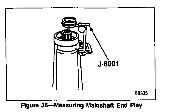
o Turn transmission on end and mount a dial indicator J 8001 on the extension housing with the indicator on the end of the mainshaft.
Measure
o Mainshaft end play (figure 36).
o Rotate the mainshaft and zero the dial indicator. Pull upwards on the mainshaft until end play is removed and record reading.
o Ideal mainshaft end play is zero with +/- 0.02 mm (0.001 inch) allowable.
o To set preload, select a shim pack equal to the dial indicator reading recorded.
26. Remove front bearing retainer (96) and front bearing race (99).
27. Install necessary shim(s) (98) and reinstall bearing race (99).
o Apply a 3 mm diameter (1/8 inch) bead of RTV sealant GM P/N 12345739 or equivalent on case mating surface of front bearing retainer.
28. Bearing retainer (96).
o Apply pipe sealant GM P/N 1052080 to the treads of the retainer bolts.
29. Retainer bolts (95).
Tighten
o Retainer bolts (95) to 20 N-m (15 lbs. ft.).
30. Drain plug.
o Apply pipe sealant GM P/N 1052080 to the treads of the drain plug.
Tighten
o Drain plug to 27 N-m (20 lbs. ft.).
31. Fill the transmission to the proper lever with Dexron IIE transmission fluid or equivalent.
32. Fill plug.
o Apply pipe sealant GM P/N 1052080 to the treads of the fill plug.
Tighten
o Fill plug to 27 N-m (20 lbs. ft.).
SPECIFICATIONS FASTENER TIGHTENING SPECIFICATIONS ------------------------------------ N-m Lbs. Ft. Lbs. In. Countershaft Retainer Bolts ...................... 20 15 - Drain Plug ....................................... 27 20 - Drive Gear Bearing Retainer Bolts ................ 20 15 - Extension Housing Bolts .......................... 30 22 - Fill Plug ........................................ 27 20 - Pivot Bolt ....................................... 27 20 - Transmission Cover Bolts ......................... 13 - 115
LUBRICATION SPECIFICATIONS
Capacity ....................................... 2.8L (2.96 qts.) Type Recommended ............................... Dexron IIE Automatic Transmission Fluid T2538
General Motors bulletins are intended for use by professional technicians, not a "do-it-yourselfer". They are written to inform those technicians of conditions that may occur on some vehicles, or to provide information that could assist in the proper service of a vehicle. Properly trained technicians have the equipment, tools, safety instructions and know-how to do a job properly and safely. If a condition is described, do not assume that the bulletin applies to your vehicle, or that your vehicle will have that condition. See a General Motors dealer servicing your brand of General Motors vehicle for information on whether your vehicle may benefit from the information.
